Start With the Motion You Need to Lock
A clamping knob for adjustable mounts should hold the chosen position without making routine adjustments awkward. Start by identifying the movement the joint allows. A sliding bracket, pivoting arm, and split collar transmit loads differently. Record the equipment weight, adjustment range, operating orientation, and expected vibration. Include cable pull and accidental contact in the design review. Then define an acceptable position change after tightening. This gives the supplier a measurable requirement beyond thread size and appearance.
Selection checks for common adjustable mount joints
| Mount joint | Main check | What to confirm |
|---|---|---|
| Sliding bracket with a slot | Seating support | Check bearing area, slot edges, and hardware at both travel limits. |
| Pivoting arm | Load offset | Provide the payload, pivot distance, and operating orientation for a capacity review. |
| Split collar on a post | Collar fit | Confirm post diameter, collar compatibility, and resistance to sliding and rotation. |
| Screw pressing against a rail | Contact geometry | Confirm the screw tip or pad suits the surface and expected pressure. |
Size a Clamping Knob for Adjustable Mounts Around the Load
Weight alone cannot describe an adjustable arm’s demand on its joint. The distance between the load and pivot also matters. For example, a 20 N force acting 0.15 m from a pivot produces a 3 N·m moment. Extending that distance to 0.30 m doubles the moment. This illustration describes the applied load, not the required tightening torque. Joint geometry, friction, preload, and material strength determine holding performance. Give the mount designer both force and offset when requesting a capacity review.
Choose the Grip Around Hand Access and Adjustment Frequency
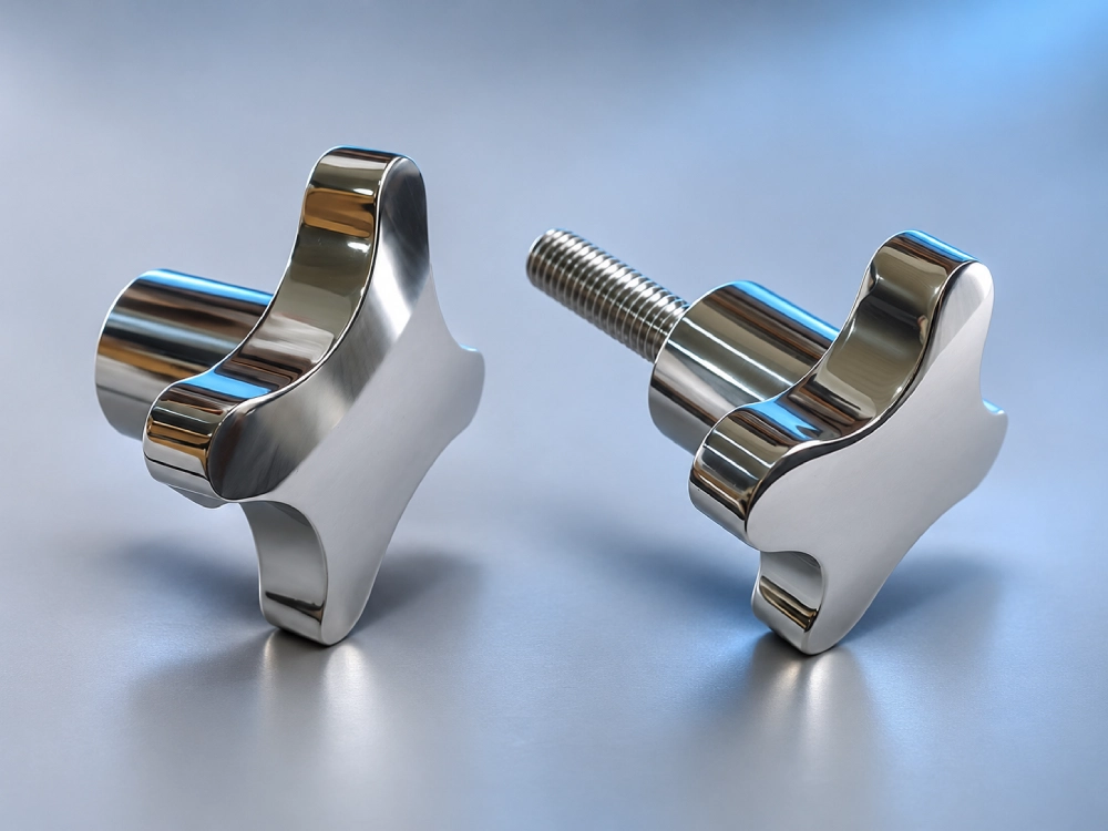
Lobed heads provide finger contact at several angles, while knurled rims offer a compact gripping surface. Compare these options with the actual hand clearance around the installed bracket. A larger head offers more leverage but also needs more turning space. For gloved operation, test access throughout the full adjustment range. MXCZ’s four-lobe clamping star knobs provide a reference for this grip style. Confirm the exact head dimensions and thread configuration before choosing a variant. Where rotation space is restricted, compare a suitable repositionable lever.
Match Threads Across the Entire Adjustment Range
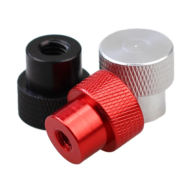
A male stud suits a tapped bracket or compatible captive nut. A female threaded head suits an existing stud. Verify diameter, pitch, thread system, and usable engagement against the assembly drawing. Check the thickest and thinnest positions in the panel stack. A long stud can bottom in a blind hole before the joint clamps. A short stud may provide inadequate engagement at maximum separation. For a through-stud arrangement, compare MXCZ’s aluminum through-hole knurled thumb nuts. Check protruding stud clearance and confirm engagement with the supplier.
Make the Contact Surface Support the Joint
On a slotted bracket, the bearing face must transfer pressure into a sufficiently supported area. A narrow seating face can deform thin sheet or damage a slot edge. Use the washer, spacer, or bearing plate specified by the mount designer. Keep that hardware flat and clear of bends or raised features. A screw pressing directly against a rail needs a different contact arrangement. A suitable swivel pad can accommodate surface angle and reduce rotational scuffing. Confirm the pad’s compatibility and pressure capacity before changing the original screw tip.
Control Slip, Droop, and Movement During Tightening
A slipping mount can have enough thread engagement yet insufficient resistance at its mating surfaces. Check contamination, contact area, joint stiffness, and load offset before selecting a larger head. Excessive tightening can bend the bracket or damage a soft insert. Distinguish movement during tightening from movement after loading. Screw rotation can drag an unsupported part away from its setting. For repeated positions, ask about a locating stop or indexing feature. Such features can improve repeatability when friction alone cannot maintain the required location.
Select Materials for Repeated Service
Match the head, insert, stud, mating thread, and contact hardware to the operating environment. Polymer heads can reduce weight, but their temperature and chemical limits depend on the specific grade. Aluminum provides another lightweight option, while stainless construction can suit suitable corrosion exposures. Check actual alloy and finish specifications. Repeated adjustment can wear threads, inserts, and contact faces even when corrosion causes no visible damage. Ask about permitted lubrication and cleaning methods. Lubrication changes thread friction and can change preload at the same applied torque.
Validate a Clamping Knob for Adjustable Mounts on a Sample
Define a sample test around the assembled mount and its actual payload. Send MXCZ the assembly drawing, thread details, joint stack, load offset, environment, and forecast quantity. Request confirmation of the selected variant and any required material records.
- Agree on displacement limits, dwell duration, and cycle counts before testing.
- Record the initial position and the tightening method.
- Measure position change immediately after tightening and again after the defined dwell.
- Repeat the check at the longest extension and other demanding orientations.
- Run representative operating and adjustment cycles, then record displacement and visible wear.
- Include the intended operators, gloves, and cleaning conditions where relevant.
Frequently Asked Questions
Why does the arm droop even though the knob feels tight?
A tight feeling can come from thread friction, bottoming, or shoulder interference before useful clamping develops. Start by checking that the seating face actually compresses the intended joint. Then inspect the pivot faces for contamination, wear, or deformation. Compare the payload and extension with the mount’s rated configuration. Moving the same load farther from the pivot increases its turning effect. If the joint still slips, ask the mount designer to review its contact geometry and holding capacity. Follow the specified tightening limit during diagnosis.
Will a larger knob let the mount carry more weight?
A larger head can increase hand leverage, but the full assembly determines load capacity. The stud, insert, bracket, and contact faces each impose limits. More hand torque can damage one component before the joint holds the intended load. Compare the replacement’s dimensions and torque limits with the original design. Ask for a capacity review using the actual payload, extension, orientation, and operating conditions. Validate the assembled sample against a defined displacement limit. For repeatable tightening, discuss a suitable torque-controlled component with the designer.
How can I keep the same position after repeated adjustments?
Identify whether you need approximate alignment or a measurable return to one location. A scale can help operators approach a setting, while a stop or locating feature can establish it mechanically. Support the mounted equipment as the joint closes to limit movement during tightening. Use the specified sequence when the assembly has multiple fasteners. Test the return position over representative adjustment cycles and record the variation. If wear increases that variation, inspect the locating surfaces and thread condition. Agree on replacement criteria for the assembly’s functional components.