
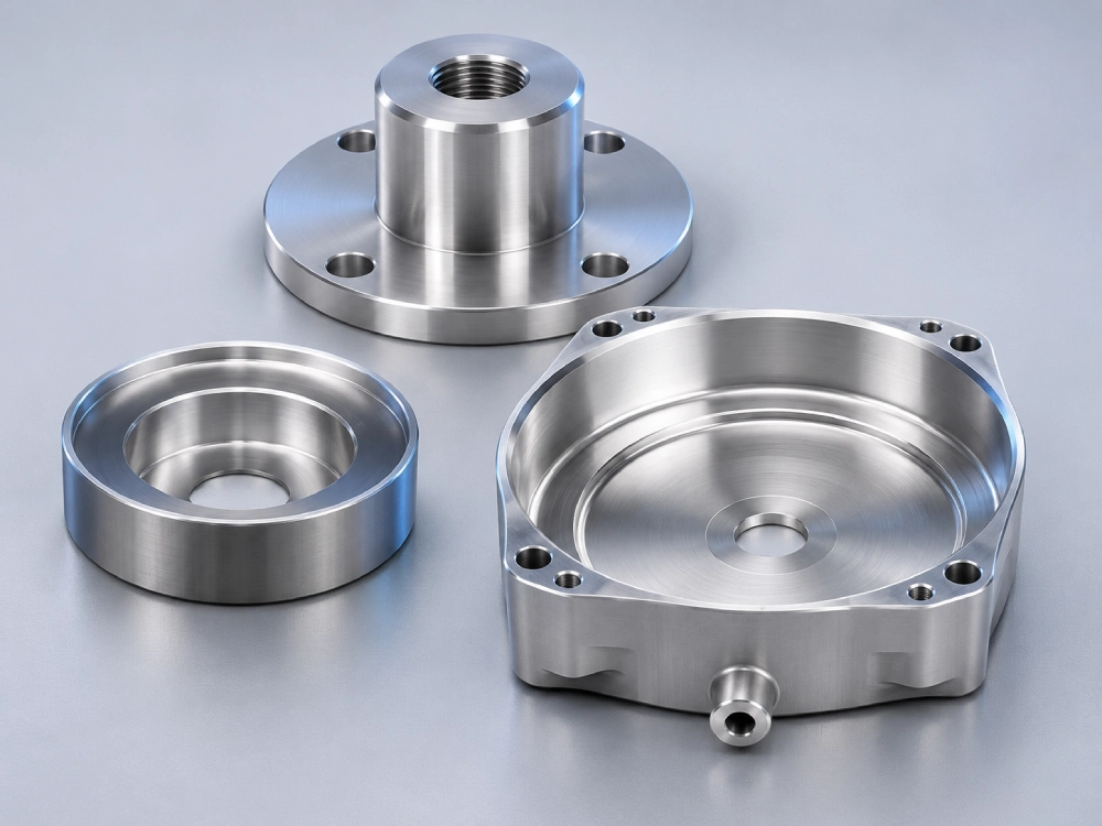
Identify the Corner Before Choosing a Dimension
CNC machining internal corner radius affects cutter access, machining time, surface finish, and how mating parts fit. A rotating end mill leaves a curved transition where two vertical pocket walls meet. The floor-to-wall transition forms a different feature and may need a different cutter. Start by identifying which corner controls assembly or function. Then review pocket depth, adjacent walls, material, and tolerances together. Allow generous radii where the design permits, while protecting clearances, sealing surfaces, and structural requirements.
Give the CNC Machining Internal Corner Radius Toolpath Clearance
The pocket radius and cutter radius describe different things. An 8 mm diameter end mill has a 4 mm radius. With a 5 mm pocket radius, its center follows a 1 mm radius through the corner. This illustrates nominal geometry rather than prescribing a cutting strategy. Matching the pocket radius exactly to the cutter radius leaves no rounded center path. The resulting engagement can force slower cutting and increase vibration. A smaller cutter can provide clearance, but its reach and stiffness also need review.
Corner geometry checks before requesting a quote
| Feature | What controls the choice | Design action |
|---|---|---|
| Vertical pocket corner | Cutter diameter, toolpath, and reach | Allow space for a rounded cutter-center path. |
| Floor-to-wall fillet | Cutter tip geometry and floor requirements | Specify its radius separately. |
| Corner beside a thin wall | Remaining material and wall support | Check local thickness before adding relief. |
| Corner receiving a mating part | Both profiles and their tolerances | Verify the full assembly clearance. |
Review Pocket Depth Alongside Radius and Material
A deep pocket with small corners can require a slender tool with substantial reach. Longer reach increases the challenge of controlling deflection and vibration. The machinist may need lighter passes, additional tools, or a different setup. Those choices affect production time and repeatability. Keep comparable radii consistent where function allows, and identify corners that genuinely need smaller values. Ask the supplier to review tool access for your precision milled components. Provide the actual grade and pocket depth. A radius-to-depth rule alone cannot establish the best process for every geometry.
Make Space for Square Mating Components
A rectangular insert can contact rounded pocket corners before its sides reach the intended position. Check both profiles together, including their dimensional and positional limits. Options include rounding the insert’s external corners or adding local pocket relief. Dog-bone and T-bone reliefs create clearance beyond the basic pocket profile. Their shapes and locations need an engineering review. Check remaining wall thickness, nearby holes, contact area, and fatigue requirements. Keep relief away from functional sealing paths unless the design explicitly accommodates it. Approve the revised geometry before machining.
Specify Floor Fillets Independently From Vertical Corners
A flat end mill and a cutter with a rounded tip leave different floor transitions. A large vertical corner radius does not automatically require a large fillet around the pocket floor. State each functional radius clearly in the drawing and CAD model. Where the mating component needs full floor contact, check its lower edge against the remaining fillet. A suitable edge break or designed relief may provide clearance. Avoid adding decorative blends across every edge without reviewing the extra machining. Small finishing tools and repeated contour passes can increase cycle time.
Connect Radius Tolerances With Fit and Inspection
Specify the acceptable radius range from the assembly requirement and the available material. A tight nominal callout can limit tool choices even when the corner has no precise function. However, a generous radius can still interfere with a mating profile. Check size, location, and adjacent surfaces together. After coating or polishing, verify the final clearance where it matters. The supplier’s stainless steel precision machined parts illustrate related housing and bracket applications. Confirm the grade, finish, and critical dimensions for your actual part. Agree on inspection access and measurement criteria before production.
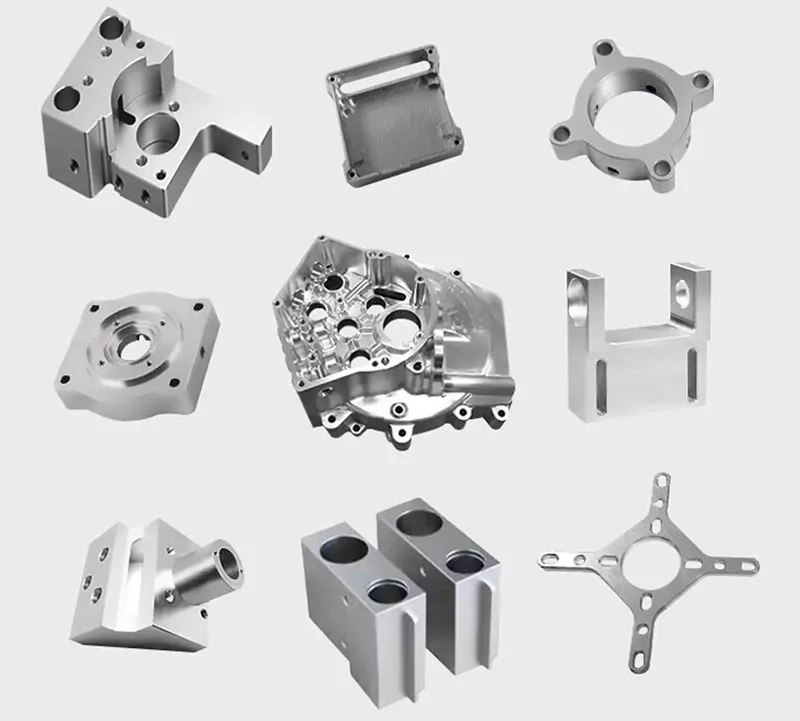
Confirm CNC Machining Internal Corner Radius Before Production
Send matching CAD and drawing revisions with material, quantity, pocket depths, finishes, and critical mating dimensions. Identify which corners engineering can enlarge and which interfaces must retain their approved geometry. Request supplier feedback on tooling, cycle time, and any secondary process. For clearance-critical assemblies, define a sample fit check alongside dimensional inspection. If a truly sharp feature is essential, discuss an appropriate alternative process and its achievable radius. Use the following checklist to settle geometry and acceptance before releasing the order.
- Identify vertical corners separately from floor fillets.
- Record depth, access restrictions, and nearby thin sections.
- Check mating-part profiles at their dimensional limits.
- Review larger radii, local relief, or changes to the mating part.
- Confirm inspection requirements after the final finish.
- Approve the sample and controlled drawing revision.
Choose the Radius From Fit, Reach, and Tool Clearance
Choose the largest corner radius that preserves the required fit, clearances, and remaining wall thickness. Give the cutter room to follow a rounded path, and review tool reach for deep pockets. Specify floor fillets separately and check the mating part at its tolerance limits. Where a square insert needs clearance, compare rounded insert edges with an approved local relief. Confirm the final geometry, finish, and sample fit with the supplier before production.
Frequently Asked Questions
Can a CNC machine produce a perfectly sharp inside corner?
A conventional rotating end mill leaves a radius in a vertical pocket corner. Reducing cutter diameter can tighten that corner, but tool reach and stiffness constrain the result. If function requires a sharper feature, discuss a suitable secondary process with the supplier. Electrical discharge machining can suit conductive materials, although it also has a finite achievable radius. Through-features and blind pockets may need different equipment and tooling. Supply the required corner limit and mating geometry so the supplier can assess access, finish, inspection, and cost.
Should I always choose a standard corner radius?
Standard cutters can produce many pocket radii through programmed tool motion. The finished radius does not have to equal the cutter’s radius. For example, a slightly larger pocket radius can give a standard cutter room to turn. Choose the geometry from fit, available material, pocket depth, and manufacturing feedback. Keep equivalent corners consistent to simplify review and potential tool reuse. Ask the supplier which alternatives change the quote meaningfully. Confirm the final drawing dimension and tolerance before accepting a proposed radius change.
How can I prevent a square insert from binding in the pocket?
Compare the insert and pocket profiles across their full tolerance ranges. Confirm that the rounded pocket corners leave clearance for the insert’s external edges. You can round those edges, enlarge the pocket locally, or add a suitable corner relief. Check that the chosen change preserves location, retention, and required bearing contact. Also inspect the floor fillet, since it can stop the insert from seating fully. Include the final finish in the clearance review. Verify the sample assembly and measure any critical gaps before approving production.