Handwheel Graduations: How to Read and Specify Them
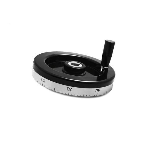
Handwheel graduations are marks around a rotating control that help an operator set or repeat a position. They may be numbered, paired with a fixed reference mark or combined with a mechanical position indicator. Their meaning depends on the mechanism behind the wheel. A scale that looks precise does not, by itself, establish the actual accuracy of a machine.
For a useful graduated control, the designer must connect each mark to shaft rotation and to the resulting movement of the controlled element. The operator also needs a reliable zero reference and a procedure for approaching the target position.
Convert rotation into movement
For a direct-drive lead screw, begin with the linear movement produced by one full revolution. Divide that movement by the number of equally spaced marks to obtain the nominal movement per division. If one revolution moves an axis 2 mm and the wheel has 100 divisions, the nominal scale increment is 0.02 mm per division. This is a reading increment, not a certified accuracy value. For industrial machine handwheels, this calculation helps determine suitable graduation spacing for the intended positioning task.
The formula changes if the handwheel drives through gears, a differential screw or another transmission. A multi-start screw also needs its actual lead, which may differ from the pitch measured between adjacent threads. The machine drawing or measured kinematics should govern the scale design.
Distinguish resolution from accuracy
More marks make a finer reading possible, but they do not remove screw lead error, gear error, thermal effects, elastic deflection or looseness. A 0.02 mm nominal division does not mean the output position is always within 0.02 mm of the intended value. Accuracy must be verified against a suitable reference over the relevant travel and conditions.
Graduations can still improve repeatability of setup when users follow a consistent method. They help record settings, communicate an adjustment and return near a previous position. Their benefit is strongest when the machine is maintained and the scale corresponds to its actual motion.
Manage backlash and approach direction
Backlash is lost motion when direction reverses in a mechanism with clearance. If an operator overshoots and immediately turns back to the target mark, the wheel may move before the controlled element does. A procedure may specify that final approach always comes from the same direction. The allowable approach depends on the machine design; the operator should not improvise a correction without a validated method.
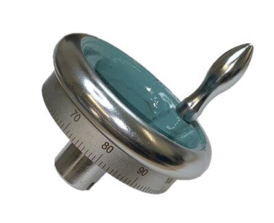
When the scale ring can be adjusted, establish zero at a known physical reference and make sure the ring is secure. Recheck after maintenance, disassembly or a change to the screw or drive train. A zero mark that has shifted can make every later reading misleading.
Design the scale for the actual task
Choose a graduation count that is readable at the expected viewing distance. Consider number placement, contrast, lighting and whether the operator wears gloves. The wheel’s rotation direction should agree with the movement the user expects, and any clockwise/counterclockwise arrows must be unambiguous. Where several revolutions are possible, add a revolution counter or position indicator if a single-turn dial could be misread.
The design drawing should identify the fixed index, the zero-setting method, the direction of increasing values and the meaning of one division. Specify whether the graduation is on the wheel, a separate ring or an indicator mounted to the spindle. Also define what happens if the knob or wheel is removed and reinstalled.
How to check a graduated handwheel
An acceptance check can verify legibility and marking alignment, then compare indicated settings with independently measured movement at selected points of travel. For aluminum solid handwheels, this check can also confirm that the markings remain clear and aligned during operation. Repeat the check in the specified approach direction and after reversal if backlash is relevant. Record the environmental and loading conditions used for a performance claim. If the application is safety-critical or closed-loop accuracy is required, a simple marked dial is not a substitute for an engineered sensing and verification system.
Work through a complete setting example
Suppose a direct-drive screw moves an axis 2 mm for each complete turn and the wheel carries 100 equal divisions. One division nominally represents 0.02 mm of axis movement. To request 0.50 mm of movement from a known reference, the operator would count 25 divisions in the specified direction. That calculation is valid only if the screw lead, drive ratio and reference are correct. It does not measure the axis or compensate for backlash.
If the adjustment can span several turns, the operator must also know the revolution count. The same dial mark appears once on every turn, so a single-turn scale cannot distinguish 0.50 mm from 2.50 mm without another reference. A mechanical revolution counter, position indicator or written setup procedure can resolve that ambiguity. In a production setting, the chosen method should be simple enough to use consistently.
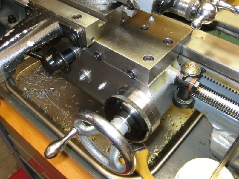
Check whether a lathe dial shows radius or diameter
On a lathe cross slide, moving the tool radially changes the workpiece diameter by twice the radial movement. If a dial indicates actual cross-slide travel, a 0.02 mm inward movement would nominally reduce the diameter by 0.04 mm. Some machines instead mark the dial to show the resulting diameter change. The operator must check the machine manual and verify the reading with a measured test cut before relying on either convention.
This distinction does not apply to every handwheel. A table-feed dial may show direct linear travel, while a rotary adjustment may need an angle or gear-ratio conversion. Describe the controlled output next to the scale so a number such as “0.02 mm per division” cannot be mistaken for a universal workpiece change.
Build an error budget before promising accuracy
The indicated increment is only one contributor to the final position. Screw lead variation, backlash, shaft coupling play, thermal growth, elastic deflection and the operator’s ability to read the mark can all matter. Which effect dominates depends on travel, load and environment. A design review should identify the required output accuracy first, then determine whether the manual dial and mechanism can meet it under test.
For a practical check, compare the commanded dial movement with an independent position measurement at several points rather than only at zero. Repeat readings while approaching from the same direction, then perform a separate reversal check. Record the spread and any systematic offset. If results differ across travel, adding more graduation marks will not repair the underlying mechanism.
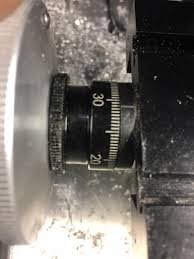
Maintain a trustworthy reference
During use, the zero position can shift if a scale ring loosens, a handwheel is removed or a drive component is replaced. A maintenance instruction should state how to establish the reference, how to secure the scale and when to verify it again. Keep the reference feature accessible and identifiable; an operator should not have to guess which edge of a painted line defines zero.
Frequently Asked Questions
Do more divisions guarantee more precision?
No. They provide a finer indicated increment; actual performance depends on the entire mechanism and its verification.
Why does the reading change after reversing direction?
Mechanical clearance can create backlash. Follow the machine’s defined approach procedure and inspect abnormal play.
Can the scale be reset to zero?
Some designs allow it, but zero should be set against a known reference and secured according to the product instructions.