Handwheels for Automation Equipment: Mechanical and Electronic Options
Handwheels for automation equipment serve defined manual tasks such as setup, changeovers, maintenance positioning or an engineered fallback mode. A buyer first needs to distinguish a mechanical wheel that transmits force from an electronic handwheel that sends commands to a controller. The machine design must then define when the control may be used, what it moves, how position is indicated and how operators are protected.
Separate the operating modes
An automated axis normally follows commanded motion. A handwheel may instead be connected mechanically to a screw or gearbox, or it may be an electronic pulse generator that sends commands to a controller. These are different devices with different risks. A mechanical wheel can transmit human force directly; an electronic handwheel depends on control logic, drive enable and speed settings.
The equipment specification should state which mode is intended. Is manual movement possible only during setup? Does the wheel remain engaged during automatic operation? Can the operator feel the load, or is it only an input device? Never infer these answers from the presence of a wheel in a photograph.
Typical uses in an automated machine
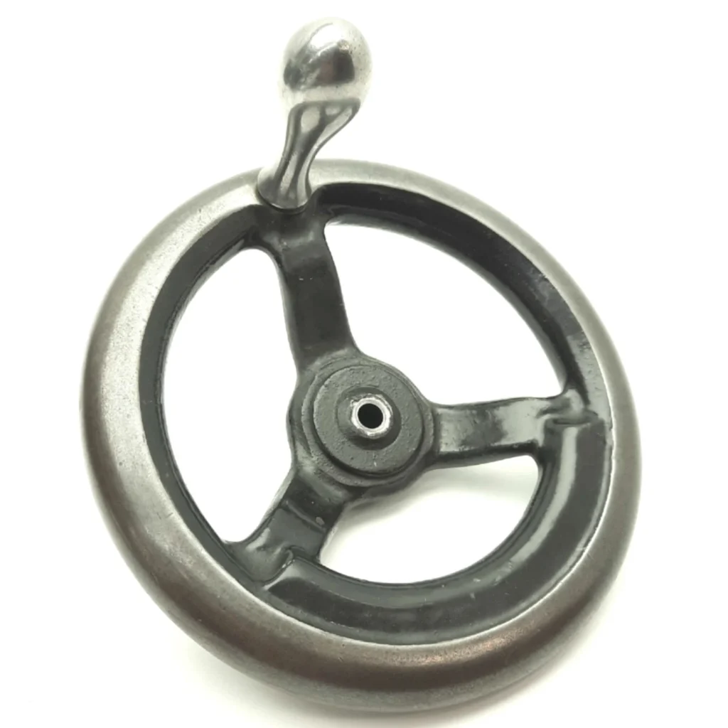
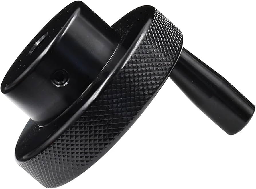
Manual controls may help align a stop, adjust a guide, position a fixture or set a process width during a product changeover. Industrial machine handwheels can also support maintenance adjustments when the machine is in an approved safe state. Some systems combine a handwheel with a mechanical or electronic position indicator so an operator can return to a known setting. The control should be located where the user can observe the relevant movement without reaching into a hazard zone.
For a repetitive setting, record the target position and the defined approach direction. If a motorized axis and a manual control share a drive train, the machine designer must specify how they are coupled and separated. An improvised retrofit can create unexpected motion or back-driving.
Design for safe interaction
Machine-specific risk assessment governs guarding, interlocks, stop functions and permitted manual modes. A handwheel should not bypass a protective device merely for convenience. If motion can occur while a person is near a pinch point, determine the allowable speed, enabling method and supervision under the applicable machine design requirements. Maintenance work may require energy isolation even when a manual positioning mode exists.
The operator needs a clear indication of which mode is active. If the control is electronic, the system should define what happens after power loss, communication failure or a mode change. If it is mechanical, verify that the wheel cannot spin unexpectedly during powered operation unless specifically designed and guarded for that condition.
Choose the physical handwheel
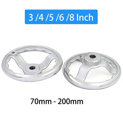
Specify diameter, hub or bore interface, grip style, material and operating clearance. A larger wheel can provide a different leverage and reach, but it can also increase the risk of overloading a screw or gearbox. The allowable operating force and torque must come from the machine design. If a revolving handle is used, include its full swept envelope and finger clearance.
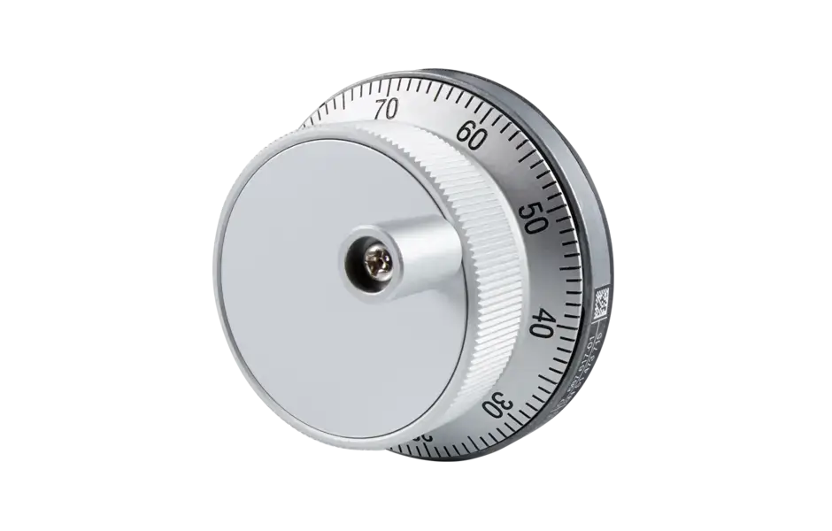
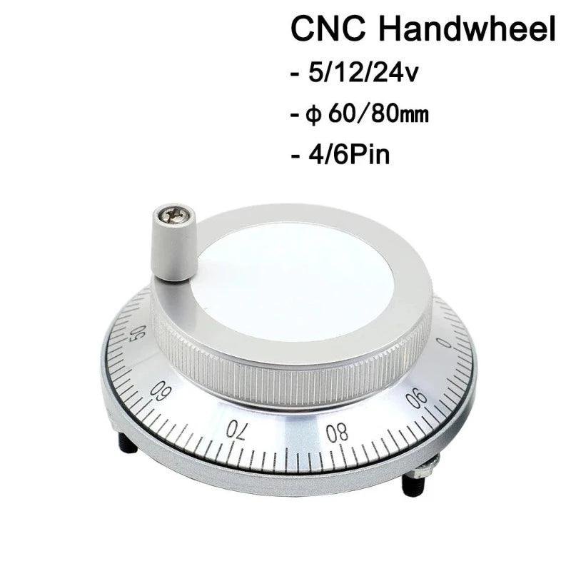
For a position-setting handwheel, decide whether graduations or a separate indicator are needed. Markings can help an operator repeat a setting, but the actual axis accuracy still depends on the transmission, backlash, calibration and load. For multi-turn positioning, a revolution count or dedicated indicator may prevent ambiguity.
Document the complete interface
A useful design package identifies the axis or setting controlled, permitted modes, direction of movement, travel limits, connection drawing, position reference, expected operation frequency and environmental conditions. Include the machine’s safety requirements and the acceptance test. For a replacement, verify that the new wheel does not change the original leverage, clearance or mode behavior without engineering approval.
During commissioning, test the indicator, travel limits and interaction with powered motion under the machine maker’s approved procedure. Record the final configuration. A handwheel that fits the shaft is not automatically suitable for the control system.
Define the handoff between manual and automatic control
The change between modes deserves a written sequence. For a mechanical handwheel, determine whether a clutch, removable wheel or other arrangement separates it from powered motion. For an electronic handwheel, define when controller input is accepted, which axis is selected and how commanded movement is limited. The machine designer should decide what the operator sees during a mode change and what happens to an unfinished command.
An unattended wheel that turns during automatic motion can create a strike or entanglement hazard. Conversely, a wheel that appears engaged but is not connected can mislead an operator during setup. These conditions require machine-specific review; the presence of a mode selector alone does not prove that the control is safe. Test the handoff under the approved commissioning plan, including loss of power and restart behavior where relevant.
Match indication to the task
If the purpose is to return a guide to a known setting, record the required unit and resolution. A simple graduated ring may be sufficient for coarse setup; a multi-turn indicator can help when several revolutions are involved. Aluminum solid handwheels may suit manual positioning systems where a lightweight, rigid control is preferred. An electronic system may show actual or commanded position, which are not necessarily the same under every fault or load condition. Label the display clearly and define how the position is referenced after maintenance or power loss.
Check rotation direction against the actual machine motion. A clockwise turn that increases a display value but moves the wrong guide can produce setup errors. For multiple axes, avoid identical controls that can be confused. The operator should be able to identify the axis, active mode and permitted travel before movement begins.
Review service and replacement needs
The wheel is part of a larger mechanism that may include a shaft, key, gearbox, indicator or electronic encoder. A spare-part request should identify the complete assembly and the interface, not only the visible wheel diameter. If a replacement changes grip size or leverage, review the effect on the mechanism and guarding. If it changes a scale or encoder, check calibration and direction before the machine returns to production.
During routine maintenance, inspect looseness, damaged grips, unreadable markings and abnormal play. Record repeated failures and investigate their cause. A wheel that repeatedly cracks or slips may be receiving loads the original design did not anticipate, or the retention method may be failing. Replacing it with a stronger-looking part without a design review can transfer the problem to a less visible component.
Frequently Asked Questions
Is a handwheel necessary on an automated machine?
Not always. It is useful only when a defined manual task justifies it and the machine integrates it safely.
Is an electronic handwheel the same as a mechanical wheel?
No. One issues control commands; the other can transmit mechanical motion directly. Their safety and interface requirements differ.
Do graduations show the exact axis position?
They indicate a nominal setting. Position must be verified against the mechanism and application requirements.