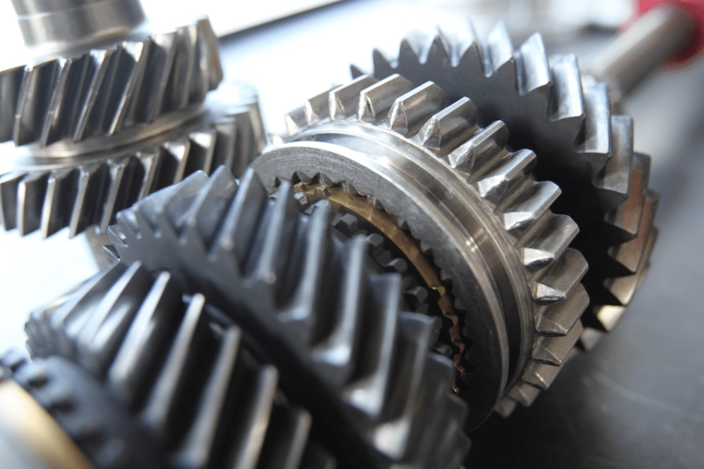
Mechanical transmission systems exhibit gear backlash as lost motion between mating gear teeth, a key factor in precision engineering. Engineers manage this parameter to control positioning accuracy in demanding applications. Motion control systems depend on tight mechanical coordination across multiple components. Excess clearance creates positioning errors and vibration issues. Designers evaluate this parameter during early transmission planning stages. Industrial automation demands stable torque transfer across operating cycles. Robotics systems require predictable response during direction changes. CNC machines rely on tight mechanical coupling for repeatable accuracy. Engineers balance efficiency and mechanical safety margins carefully throughout design. Temperature variation also influences gear engagement behavior significantly. Material expansion changes tooth spacing under load conditions. Assembly alignment further impacts system stability and repeatability. Designers must evaluate all variables together before final specification. Proper control improves system repeatability and reduces mechanical drift over time.
Fundamentals in Precision Applications
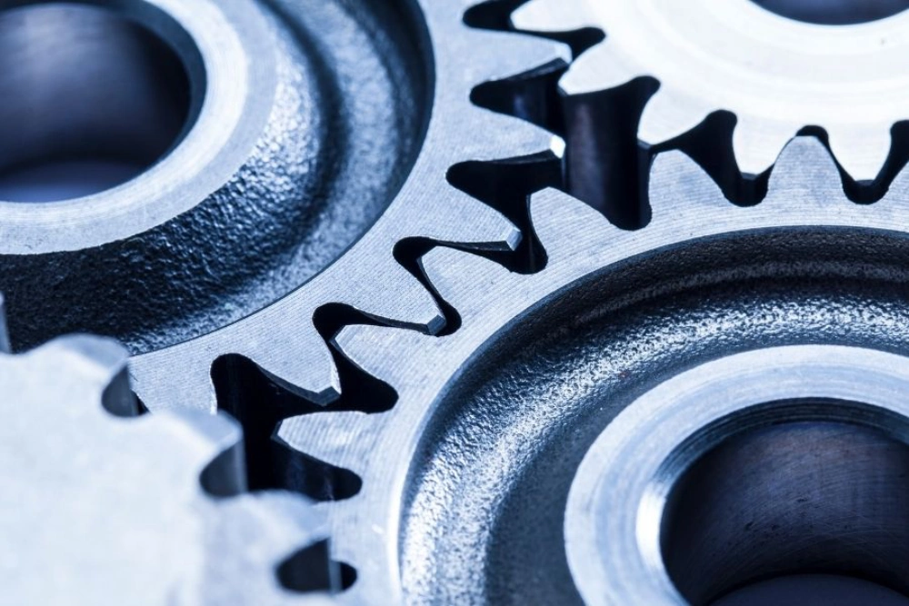
Mechanical transmission systems use controlled clearance between gear teeth. This clearance defines motion loss before torque transfer begins. Engineers measure backlash in arc minutes or micrometers. Each system requires a specific tolerance range. High precision assemblies demand minimal clearance for stable motion. Heavy-duty systems tolerate higher values for durability. Designers evaluate load cycles and speed profiles carefully. System stiffness also influences acceptable limits. Lubrication conditions affect contact stability during operation. Manufacturing precision directly shapes final performance. Engineers often simulate meshing behavior before production. Dynamic forces create variation during acceleration phases. Controlled backlash improves repeatability in closed-loop systems. Overly tight designs increase wear and heat generation. Balanced specification ensures stable long-term operation.
How To Select Gear Backlash For Precision Applications? Design Principles
Engineers select gear backlash by analyzing system accuracy requirements. Motion systems demand predictable positioning under varying loads. Control systems use feedback loops for correction. Designers calculate allowable deviation before final specification. High precision assemblies require tighter tolerances. Lower precision systems allow wider clearance ranges. Material selection influences elastic deformation behavior. Shaft rigidity affects gear meshing stability. Engineers also evaluate noise and vibration levels. Reduced clearance improves positional response but increases friction risk. Thermal expansion changes operational spacing significantly. Environmental conditions also impact long-term performance. Assembly methods influence final alignment quality. Engineers optimize balance between efficiency and accuracy. Proper selection reduces system error accumulation over time.
High Precision Applications Selection Strategy
Selection strategy depends on torque demand and motion profile. Engineers evaluate acceleration cycles and reversal frequency. High-speed systems require stable meshing under dynamic load. Low-speed systems prioritize positional repeatability. Control algorithms compensate for minor mechanical deviation. Designers analyze stress distribution across tooth surfaces. Precision bevel gear worm gear configurations require careful evaluation of load transfer characteristics. Manufacturing variation introduces unavoidable tolerances. Engineers adjust design margins to compensate accordingly. Proper lubrication stabilizes contact behavior during operation. Assembly calibration ensures alignment consistency. System rigidity reduces deformation under load. Engineers also consider maintenance intervals and wear rates. Over time, backlash increases due to material fatigue. Regular inspection maintains performance consistency. Proper selection ensures long-term operational reliability.
Material and Manufacturing Effects on Gear Backlash
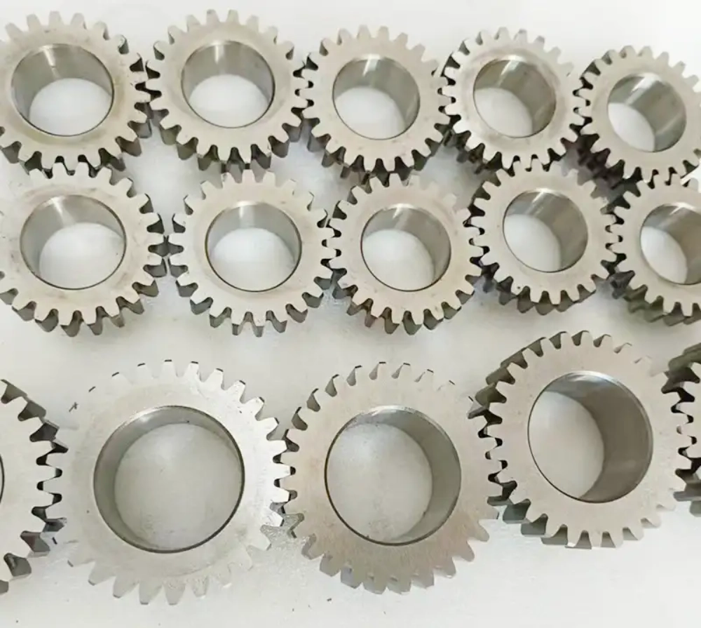
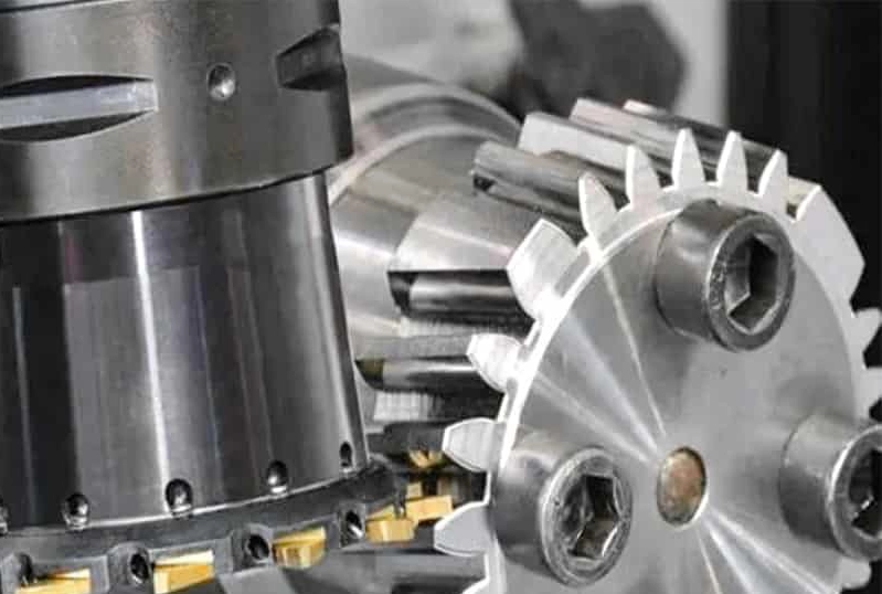
Material selection strongly influences deformation under load. Hardened steel provides high rigidity and stability. Polymer gears reduce noise but increase elasticity. Manufacturing accuracy defines final tooth geometry precision. CNC machining improves dimensional control significantly. Heat treatment affects hardness and distortion behavior. Engineers compensate for shrinkage during processing. Surface finishing improves meshing smoothness and stability. Assembly error contributes to final clearance variation. Tolerance stacking increases system uncertainty. Designers analyze cumulative deviation carefully. Environmental temperature shifts also alter spacing. Proper quality control reduces variation across batches. Precision manufacturing ensures repeatable system performance. Engineers integrate feedback from testing into final adjustment.
Gear Backlash Measurement and Standards in Engineering Systems
Engineers measure clearance using dial indicators and coordinate measuring machines (CMM). Measurement accuracy determines validation quality. ISO 1328-1 defines allowable gear tooth errors for spur and helical gears, while AGMA 2015-A88 sets standards for tooth thickness and backlash in precision gears. Testing ensures compliance with these performance requirements. Gear inspection includes radial and angular checks. Backlash measurement evaluates functional motion loss. Engineers record data under controlled temperature conditions. Load testing verifies real operational behavior. Calibration ensures repeatable measurement accuracy. Digital systems improve inspection speed and precision. Data logging supports quality traceability across production. Standards ensure consistency across global manufacturing.
Engineers use statistical analysis for batch validation. Proper measurement reduces system uncertainty significantly. Reliable inspection supports long-term performance assurance.
Optimization Methods for Gear Backlash in Precision Applications
Application Comparison Table for Gear Backlash Selection
| Application Type | Typical Requirement | Backlash Level | Design Focus |
|---|---|---|---|
| Industrial Robotics | High positional accuracy | Very Low | Repeatability and control stability |
| CNC Machinery | Precision cutting motion | Low | Dimensional accuracy and rigidity |
| Automotive Systems | Torque transmission | Medium | Durability and load handling |
| Heavy Industry Drives | High torque loads | Moderate to High | Strength and wear resistance |
Application environments define design priorities clearly. Robotics systems demand tight positional feedback control. CNC systems prioritize machining accuracy and repeatability. Automotive systems balance efficiency with durability requirements. Industrial drives focus on torque handling capability. Engineers adjust specifications based on load cycles. Control algorithms further refine motion accuracy in practice. Proper selection improves operational efficiency across industries. System integration ensures stable long-term performance. Designers evaluate real-world constraints before final approval.
Best Practices List for Backlash Control in Engineering
- Engineers optimize gear geometry during early design stages
- Manufacturing teams maintain strict machining tolerances
- Assembly teams calibrate alignment during installation
- Maintenance teams inspect wear at regular intervals
- Designers simulate thermal expansion before final specification
- Control systems compensate for minor mechanical variation
Design teams integrate multiple disciplines for reliable performance. Each practice reduces uncertainty in mechanical behavior. Engineers coordinate between design and manufacturing teams. Maintenance feedback improves long-term system reliability. Simulation tools support accurate prediction of system response. Proper execution ensures stable performance across operating cycles.
System Integration Analysis
System integration determines final performance behavior under real conditions, including gear backlash influence. Engineers combine mechanical and control system design. Motion controllers adjust for minor mechanical deviation. Sensor feedback improves positioning accuracy continuously. Thermal effects influence long-term stability significantly. Assembly alignment determines baseline system precision. Spur gear helical gear assemblies require precise alignment to maintain consistent motion. Engineers validate performance under dynamic load conditions. Testing confirms system response under real operation. Calibration improves consistency across production units. Wear behavior changes performance over lifecycle stages. Proper integration reduces cumulative error accumulation. Engineers optimize both hardware and software together. Stable coordination improves efficiency and reliability. Final validation ensures compliance with engineering requirements.
Thermal and Dynamic Influences on Stability
Temperature variation directly affects gear spacing behavior. Expansion changes tooth engagement geometry significantly. High-speed operation introduces dynamic load fluctuations. Engineers analyze vibration impact on meshing stability. Material stiffness reduces deformation under stress. Lubrication performance varies with temperature changes. System design compensates for environmental variation. Control systems stabilize motion under changing loads. Engineers simulate thermal cycles during development. Field testing validates real operating conditions. Structural rigidity improves resistance to deformation. Proper thermal design ensures stable performance. Dynamic analysis reduces unexpected system variation. Engineers refine models using real-world feedback.
Wear Behavior and Lifecycle Impact
Wear gradually increases clearance between mating gears. Surface fatigue develops under repeated load cycles. Engineers track degradation through maintenance schedules. Lubrication reduces friction-induced wear significantly. Material hardness determines wear resistance levels. Surface treatments extend operational lifespan. Engineers design for predictable degradation patterns. Monitoring systems detect performance drift early. Replacement schedules maintain system reliability. Controlled wear behavior ensures stable operation. Design margins account for long-term changes. Engineers evaluate lifecycle cost during selection. Predictive maintenance improves system availability. Proper design reduces unexpected failure risk.
FAQ
Why does gear backlash matter in precision motion systems?
Gear backlash directly affects positioning accuracy in motion systems. Excess clearance creates delay during directional changes. This delay reduces repeatability in high precision applications. Robotics systems depend on stable motion feedback loops. CNC machines require consistent tool positioning accuracy. Engineers minimize backlash to reduce control error accumulation. Reduced clearance improves system responsiveness and stability. However, overly tight designs increase wear and heat. Proper balance ensures both durability and accuracy. Control systems compensate partially for mechanical deviation. Mechanical design still defines baseline system performance limits. Engineers consider backlash during early system architecture planning. Effective control improves long-term operational consistency significantly.
How much gear backlash is acceptable for CNC equipment?
CNC systems typically require very low backlash levels. Acceptable ranges depend on machine size and accuracy class. High-end machining centers demand near-zero mechanical clearance. Engineers specify tolerances based on cutting precision requirements. Thermal expansion also affects acceptable limits significantly. Control systems reduce visible error during operation. However, mechanical design still defines baseline accuracy. Smaller machines often require tighter tolerances than large systems. Engineers evaluate spindle load and axis dynamics carefully. Calibration ensures consistent performance across production cycles. Regular maintenance helps maintain specified accuracy levels. Wear gradually increases clearance over time. Proper design minimizes long-term deviation impact. Selection depends on application precision requirements.
Can gear backlash be completely eliminated in real systems?
Complete elimination of backlash is not practical in real systems. Mechanical clearance is necessary for lubrication and thermal expansion. Engineers reduce backlash to minimal functional levels instead. Preloading techniques help control unwanted motion. Precision manufacturing reduces geometric variation significantly. However, material deformation still introduces small movement. Control systems compensate for residual mechanical error. Temperature changes also prevent absolute elimination. Wear over time increases clearance gradually. Designers accept minimal backlash as engineering trade-off. Over-constrained systems may fail under load. Balanced design ensures stable long-term performance. Engineers prioritize controlled behavior over absolute zero clearance. Practical systems always maintain measurable but controlled backlash.