Load And Torque Definition In How to specify a gear For Mechanical Systems
Accurate torque evaluation defines the foundation of reliable gear design in industrial applications. Engineers must first determine transmitted load, peak shock conditions, and continuous duty cycles. When considering how to specify a gear, early load analysis ensures that peak stresses are managed effectively. Incorrect estimation leads to surface pitting, tooth fracture, and premature fatigue failure. Safety factors must be applied based on operating uncertainty and dynamic amplification. Duty classification also influences sizing decisions in continuous or intermittent systems. Material stress limits must align with expected torque fluctuations. System designers often validate load assumptions using simulation tools and empirical testing. Proper alignment between motor output and driven load ensures stable operation under variable conditions. Environmental influences such as vibration and misalignment also affect torque distribution. These combined factors ensure long-term mechanical integrity and reduce maintenance interruptions.
Material Engineering Decisions In Gear Performance Design
Material selection directly influences durability, fatigue resistance, and thermal stability in gear systems.Alloy steels provide high tensile strength and are widely used in heavy-load environments.Stainless steel offers corrosion resistance in humid or chemical conditions.Hardened polymers may be used for low-load, noise-sensitive applications.

Heat treatment processes such as carburizing increase surface hardness while preserving core toughness. Nitriding enhances wear resistance without significant dimensional distortion. Material grain structure affects crack propagation under cyclic stress. Thermal conductivity also influences heat dissipation during continuous operation. Engineers evaluate cost-performance balance when selecting materials for industrial deployment. Proper pairing of mating gears ensures balanced wear patterns and reduces premature failure risks.
Gear Ratio Optimization And System Efficiency Control
Gear ratio selection determines output torque, rotational speed, and overall system efficiency. A higher ratio increases torque but reduces output speed, while a lower ratio improves speed at the expense of force. Engineers apply principles of how to specify a gear to ensure ratio selection aligns with real operational conditions. Efficiency in power transmission depends on friction losses, alignment precision, and load distribution. Excessive ratio selection may increase heat generation and reduce mechanical lifespan. Engineers must also consider backlash effects during directional changes. Proper ratio matching improves responsiveness and reduces mechanical stress. Lubricant viscosity contributes significantly to energy loss reduction. Contact surface finish further influences efficiency levels. High precision machining ensures smoother meshing between teeth. Operational stability improves when ratio design aligns with real-world load cycles.
| Gear Ratio Range | Typical Application | Performance Impact |
|---|---|---|
| 1:1 to 3:1 | High-speed systems | Low torque increase, high efficiency |
| 4:1 to 10:1 | General machinery | Balanced torque and speed control |
| Above 10:1 | Heavy-duty equipment | High torque, reduced output speed |
System Efficiency Analysis In Gear Ratio Design Context
Efficiency in power transmission depends on friction losses, alignment precision, and load distribution. Excessive ratio selection may increase heat generation and reduce mechanical lifespan. Engineers must also consider backlash effects during directional changes. Proper ratio matching improves responsiveness and reduces mechanical stress. Lubricant viscosity contributes significantly to energy loss reduction. Contact surface finish further influences efficiency levels. High precision machining ensures smoother meshing between teeth. Operational stability improves when ratio design aligns with real-world load cycles.
Tooth Geometry And Contact Mechanics In Gear Systems
Tooth profile design controls load distribution, noise generation, and contact stability in gear assemblies. The involute profile ensures constant velocity ratio during meshing. Module selection determines tooth size and strength capacity. Pressure angle influences radial and axial force distribution. Incorrect geometry leads to uneven stress concentration and vibration. Contact ratio defines how many teeth share load simultaneously. Higher contact ratio improves smoothness and reduces wear rate. Manufacturing precision directly affects geometry accuracy. Surface finishing reduces friction and improves engagement quality. Engineers simulate contact patterns under operational load conditions.
| Parameter | Function | Effect on Performance |
|---|---|---|
| Module | Tooth size control | Strength and load capacity |
| Pressure Angle | Force direction control | Stability and bearing load |
| Contact Ratio | Load sharing index | Smoothness and durability |
Tooth Geometry Evaluation In Industrial Gear Mechanisms
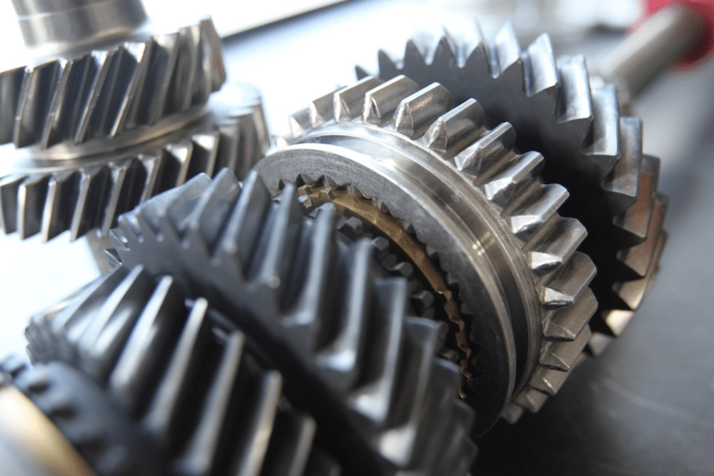
Precise geometry control ensures stable meshing and reduces mechanical noise. Spur gear helical gear configurations show different load behavior patterns under identical torque conditions. Helical designs distribute load gradually, while spur structures engage more abruptly. Geometry optimization reduces stress peaks during engagement cycles. Finite element analysis helps validate tooth strength under real operating conditions. Manufacturing accuracy remains critical for long-term reliability. Proper inspection ensures geometry consistency across production batches.
Manufacturing Tolerances In How to specify a gear For Precision Systems
Tolerance specification defines allowable deviations in dimension, form, and alignment during gear production. When considering how to specify a gear, tolerance planning ensures that dimensional variations do not compromise load distribution. International standards such as ISO 1328 for gear accuracy grades and DIN 3961 for involute gear tolerances define classification levels for industrial applications and specify permissible deviation limits for profile, pitch, and runout. Tight tolerances improve accuracy but increase manufacturing cost. Loose tolerances may reduce performance consistency under load variation. Standards such as ISO and DIN define classification levels for industrial applications. Backlash control ensures smooth directional transitions without excessive play. Surface roughness affects friction and wear rate significantly. Coordinate measuring systems validate dimensional accuracy during inspection. Heat treatment distortion must be accounted for during machining stages. Proper tolerance allocation balances cost and performance requirements.
Precision Bevel Gear Worm Gear configurations require stricter tolerance control due to complex contact geometry. Misalignment in such systems leads to significant efficiency loss and thermal buildup. Engineers apply multi-stage inspection processes to maintain dimensional stability. Advanced CNC machining improves repeatability across production batches. Quality assurance ensures compliance with international standards. Proper tolerance strategy extends operational lifespan and reduces maintenance frequency.
Lubrication Strategy And Environmental Impact On Gear Systems
Lubrication plays a critical role in reducing friction, heat, and surface wear in gear assemblies. Oil viscosity must match operating temperature and load conditions. Grease lubrication is suitable for low-speed and sealed environments. Contamination from dust or moisture reduces lubricant effectiveness significantly. Thermal degradation affects viscosity stability over time. Proper sealing systems prevent ingress of foreign particles. Lubricant film thickness determines contact surface protection level. Maintenance schedules ensure consistent lubrication performance. Environmental temperature fluctuations also influence lubrication behavior. Engineers must evaluate lubricant compatibility with selected materials.

| Lubrication Type | Operating Condition | Main Benefit |
|---|---|---|
| Oil Bath | High-speed systems | Efficient heat dissipation |
| Grease | Low-speed enclosed systems | Low maintenance requirement |
| Oil Mist | Continuous heavy-duty systems | Reduced friction and wear |
Lubrication Performance Optimization In Industrial Gear Design
Effective lubrication reduces surface fatigue and improves transmission efficiency. Film formation prevents direct metal contact under load conditions. Additive formulations enhance anti-wear performance. Temperature stability ensures consistent viscosity behavior. Proper lubrication selection extends service life significantly. Monitoring systems detect degradation trends early. Maintenance planning reduces unexpected downtime.
Quality Inspection And Reliability Validation Methods
Inspection processes ensure gear systems meet design specifications and operational requirements. Engineers consider how to specify a gear during inspection to verify that all critical tolerances and load capacities are met. Coordinate measuring machines verify dimensional accuracy with micron-level precision. Hardness testing confirms material treatment effectiveness. Surface roughness measurement evaluates friction potential. Runout analysis detects rotational deviation during operation. Non-destructive testing identifies internal material defects. Statistical quality control ensures batch consistency. Proper documentation supports traceability in industrial supply chains. Validation testing simulates real-world load conditions. Reliability assessment reduces long-term operational risk.
Common Specification Errors In Industrial Gear Design
Design errors often originate from incorrect load estimation and poor material selection. Ignoring thermal expansion leads to misalignment under operating temperature. Inadequate lubrication planning increases wear rate significantly. Overlooking manufacturing tolerance accumulation reduces system precision. Improper backlash control causes vibration and noise issues. Incorrect ratio selection affects efficiency and torque balance. Poor inspection planning allows defective components to pass quality checks. Engineers must integrate all parameters during early design stages. Systematic validation prevents costly redesign and downtime.

FAQ
How do engineers approach gear selection in early design stages?
Engineers begin by analyzing load conditions, torque demand, and expected service life. They also integrate speed requirements and environmental constraints early in the process. Material compatibility is assessed based on stress, wear, and corrosion risks. Initial calculations define gear size and ratio range. Simulation tools help validate early assumptions. Prototype testing may follow to confirm theoretical models. Manufacturing constraints are considered during planning. Cost analysis ensures feasibility. All parameters are incorporated into a preliminary specification model. This structured approach reduces failure risks and improves system reliability.
What standards are commonly used in gear specification?
Industrial gear specification relies on ISO, DIN, and AGMA standards. Engineers use these standards to select appropriate tolerances, materials, and performance ratings. ISO standards focus on global compatibility and dimensional consistency. DIN standards emphasize precision engineering practices in mechanical systems. AGMA provides detailed guidelines for load rating and stress analysis. Engineers select standards based on application region and industry type. Compliance ensures interoperability and quality assurance. Standardized methods reduce production variation and support global supply chain consistency.
What are the most critical factors in gear design?
Critical factors include torque capacity, material strength, and tooth geometry. Engineers also consider lubrication strategy, manufacturing tolerances, and heat treatment for performance stability. Manufacturing tolerance directly affects precision and noise levels. Environmental conditions influence long-term durability. Gear ratio selection determines system efficiency and output behavior. Surface finish and thermal treatment enhance wear resistance. Inspection methods ensure compliance with design intent. Each factor must be balanced within system constraints. Integrated consideration of all variables ensures reliable operation and extended service life.