Essential Reasons to Calculate Coupling Torque Correctly
Power transmission systems rely heavily on robust mechanical connections. Engine shafts must transfer rotational energy to driven components without losing power. Engineers face critical challenges when choosing the right connecting hardware for heavy industrial machinery. You must calculate coupling torque accurately during the early design phase. Unbalanced rotational forces quickly degrade delicate mechanical parts. Misalignments create excessive vibration and destroy expensive bearings. Correct math prevents premature component wear in dynamic environments. Proper planning ensures that your transmission system operates at peak efficiency. Highly demanding factory environments require robust engineering solutions. Reliable operation always depends on precise torsional measurements. Safe production areas start with exact engineering calculations. Accurate physical parameters guarantee long-term machine stability and safety. Industrial facilities experience major savings when hardware performs reliably.
Engineering Standards and Service Factors in Shaft Alignment
International organizations establish strict standards for mechanical component selection. Modern factories follow DIN 740 regulations to secure rotational components. These standards define how engineers evaluate peak loads under varied conditions. Operators must evaluate potential shock factors to avoid catastrophic system failures. Engineers choose a stainless steel torque rating coupling to provide excellent corrosion resistance under tough circumstances. High-moisture environments demand these specialized stainless components. Standard applications often use carbon steel alternatives. Different materials exhibit unique fatigue limits under cyclic loading. System designers must assess environmental factors alongside basic mechanical dimensions. Proper material selection prevents stress cracking during continuous operation. Highly corrosive chemical plants rely on specific material standards. Accurate alignment metrics prolong machine life significantly.
Mathematical Formulas and Physical Variables of Power Transmission
Mechanical power calculations require specific physical inputs. System designers require the input speed in revolutions per minute. Motor power in kilowatts forms the base of this mathematical equation. Designers utilize the standard formula where torque equals constant factors multiplied by power. You must calculate coupling torque using these precise inputs to avoid design errors. Service factors adjust the final value based on operational severity. Electric motor drives require lower service factors than diesel engines. Reciprocating pumps create heavy pulsations during daily operation. These shock loads demand additional safety margins. Overlooking these variables leads to rapid hardware degradation. Mechanical engineers always prioritize torque accuracy over simple estimations. Precise calculations guarantee successful power transmission.
Crucial Steps to Calculate Coupling Torque for Heavy Machinery
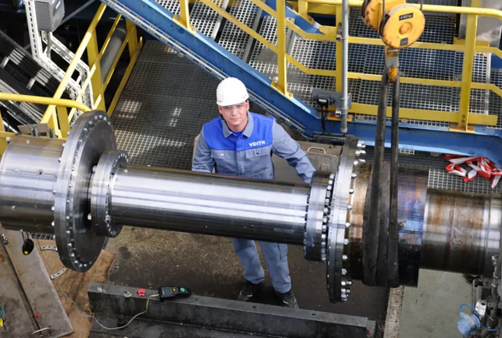
Heavy industrial applications involve massive inertial forces during startup. Motors pull high initial current to rotate static machinery. Peak starting load often exceeds normal operating load by several times. Engineers map the torque curve across all operational speeds. You must identify potential resonance frequencies during critical phases. Torsional vibration can destroy shafts without warning. Proper dynamic balancing protects surrounding mechanical components. Operators should monitor physical resistance during test runs. Mechanical limits must align with actual operating demands. Experienced teams verify alignment parameters using modern laser tools. These systematic verification steps prevent unexpected component damage. Reliable plants always prioritize comprehensive technical assessments. Dynamic stress analysis ensures long-term reliability under variable stress.
| Coupling Category | Torque Range (Nm) | Torsional Stiffness | Primary Application |
|---|---|---|---|
| Disc Coupling | 100 - 150,000 | High | High-speed compressors |
| Gear Coupling | 1,000 - 5,000,000 | Very High | Heavy steel mills |
| Bellows Coupling | 0.1 - 10,000 | High | Precision servo systems |
Deep Technical Analysis of Metallic Performance Values
The performance chart displays crucial mechanical differences between common metallic options. Designers must calculate coupling torque accurately to select the correct metallic class. Gear couplings handle extreme loads because they utilize interlocking teeth. Disc units provide exceptional torsional stiffness without requiring lubrication. Servo systems rely on bellows for absolute positioning accuracy. Each mechanical design demands a specific balance of strength and flexibility. Selecting an incorrect category triggers premature machine breakdown. Engineers evaluate these options based on continuous speed and misalignment. Precise selection reduces maintenance costs over the equipment lifecycle. Heavy industrial operations demand robust components to prevent costly downtime. Choosing the right material grade ensures safe operation. System security depends heavily on these mechanical decisions.
| Elastomer Type | Durometer (Hardness) | Temperature Range (°C) | Damping Capability |
|---|---|---|---|
| Polyurethane | 92 Shore A | -30 to 80 | Moderate |
| Hytrel | 55 Shore D | -50 to 120 | Low |
| EPDM | 70 Shore A | -40 to 149 | High |
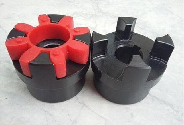
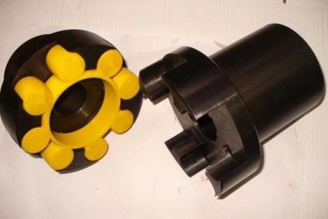
Detailed Interpretation of Elastomeric Load Limits and Alignment
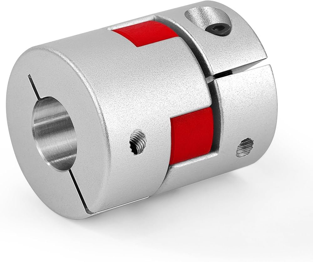
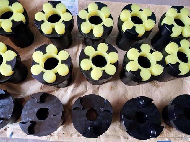
Elastomeric insert values dictate how systems manage rotational vibration. Engineers must calculate coupling torque accurately before choosing specific hardness levels. Harder materials transmit higher torque but offer less vibration damping. Softer elastomers protect delicate motor shafts by absorbing mechanical energy. Operating temperature severely affects elastomer performance and lifespan. High temperatures cause materials to soften and wear prematurely. Cold environments make elastomers brittle and prone to cracking. Correct application specifications prevent sudden material fatigue. Maintenance teams inspect these inserts during regular plant checks. Regular replacement schedules keep production lines running smoothly. Accurate mechanical planning leads to predictable performance. Proper dynamic design limits unexpected structural failures. Industrial operations secure great benefits from balanced systems.
Primary Industrial Consequences of Incorrect Torsional Selection
Industrial operations face severe risks when torque ratings do not match system requirements.
Shaft Shear: Excessive stress snaps solid steel shafts instantly.
Bearing Destruction: High radial loads wear down precision bearings.
Keyway Failure: Continuous slip deforms metal keys and keyways.
Motor Burnout: Excessive mechanical resistance overheats electrical components.
Mechanical Implications of Fatigue and Overload Failures
Specific critical failure modes demonstrate the dangers of poor calculation. Unplanned downtime costs industrial facilities thousands of dollars per hour. Physical shockwaves propagate backward through the drivetrain during failure. Motor windings melt when shafts seize under heavy mechanical resistance. Cracked housings require complete equipment replacement in severe cases. Preventing these hazards demands strict adherence to engineering principles. Accurate initial designs save significant capital over several years. Quality components resist fatigue much better than cheap alternatives. Technical safety standards protect technicians working near high-speed machinery. Safe operations rely on consistent mechanical integrity. Thorough engineering reviews eliminate potential system vulnerabilities. Industrial plants remain profitable when mechanical issues decrease. Continuous optimization secures competitive advantages for modern manufacturers.
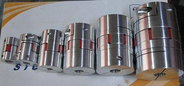
Modern Monitoring Methods for Dynamic Load Distribution
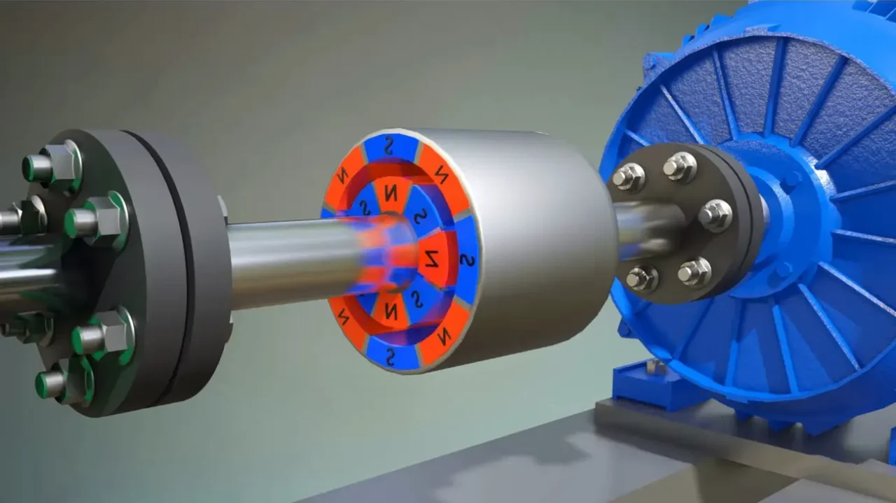
Modern factories implement real-time monitoring tools on critical production lines. Dynamic telemetry systems measure rotational strain during continuous operation. These advanced sensors alert maintenance crews before components exceed yield strength. Telemetry tools provide actual performance metrics under variable factory conditions. A flexible coupling elastomeric coupling accommodates substantial parallel misalignment without losing efficiency. Synthetic inserts dampen dynamic spikes to preserve delicate motor components. High-precision laser alignment tools verify shaft positions during installation. Technicians adjust positioning parameters to match exact thermal expansion specifications. Correct initial settings prevent unexpected axial thrust issues. Mechanical monitoring ensures consistent uptime in complex modern facilities. Advanced diagnostic software detects microscopic defects before failure occurs. Reliable engineering solutions drive long-term industrial success.
FAQ
What occurs when coupling torque calculations fall below actual system demands?
Insufficient calculations lead to instantaneous mechanical failures. High rotational forces exceed the yield strength of metal or elastomer components. Solid steel shafts shear under sudden peak loads. Rubber elements disintegrate when torque values surpass maximum limit thresholds. These failures cause unexpected production stoppages in industrial facilities. Broken components can damage surrounding motor hardware. Bearing housings crack under excessive radial forces. Operators face high replacement expenses when machines break. You must calculate coupling torque properly to prevent these safety hazards. Thorough technical planning ensures consistent machine reliability. Proper design parameters secure long-term system integrity.
How does the service factor influence industrial torque calculations?
Service factors act as safety margins for mechanical components. Driven machines experience different shock levels depending on application types. High-vibration environments like rock crushers require high service factors. Electric motors driving constant centrifugal pumps require minimal safety adjustments. Engineers multiply nominal torque by these factors to find design limits. Overlooking safety factors causes rapid material fatigue and mechanical wear. Accurate factor selection depends on daily operation hours and power sources. Internal combustion engines generate heavier pulsations than electric drives. Proper classification prevents unexpected downtime on assembly lines. Thorough engineering analysis ensures long-term operational success. Dynamic plants prioritize precise math over generic estimates.
Which coupling types offer the highest torsional stiffness for high-torque applications?
Metallic disc and gear couplings provide the highest torsional stiffness. These rigid styles utilize solid metal components instead of rubber inserts. Gear designs transmit massive torque by employing interlocking gear teeth profiles. Disc models utilize thin stainless steel sheets to handle high speeds. High torsional stiffness ensures precise shaft synchronization in manufacturing lines. Precision machinery requires absolute stability during rapid start and stop cycles. Selecting high-stiffness options prevents rotational lag between coupled shafts. Heavy industrial facilities utilize these systems for extreme load applications. Proper mechanical engineering ensures that hardware matches operational speeds. Careful engineering choices prevent premature wear on gear tooth flanks.