Selecting High-Performance Industrial Shaft Connectors
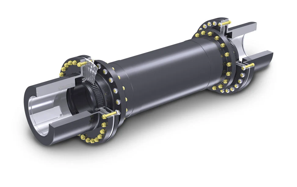
Modern industrial plants require reliable power transmission systems to maintain continuous operations. Engineers must evaluate mechanical connectors carefully to prevent unexpected equipment downtime. A premium diaphragm coupling offers excellent torsional stiffness for high-speed turbomachinery. This robust component accommodates multiple alignment errors without generating high reaction forces on bearings. Heavy machinery manufacturers prefer metallic elements because they endure harsh environmental conditions. Proper selection ensures optimal power flow and protects sensitive driving units from damage. Plant operators achieve better efficiency when they match mechanical specifications to specific load demands. Industrial processes demand continuous performance under extreme pressure and fluctuating speed variations. Selecting the right metal connector prevents expensive breakdowns in critical rotational equipment. Our review highlights the primary parameters for securing reliable torque transmission.
Crucial Torque Factors in Diaphragm Coupling Selection
Calculating system torque constitutes the first step in sizing your metal flexible connector. Designers must determine the nominal torque by using standard motor power formulas. Application service factors then multiply this value to account for shock loads. High-torque operations like reciprocating pumps demand larger service factors than smooth generators. Peak torque events during motor startup also require careful evaluation to prevent plastic deformation. Manufacturers specify maximum torque limits based on the yield strength of the metal discs. Exceeding these limits causes premature fatigue and risks catastrophic failure of the drive train. Safe operations rely on maintaining a comfortable safety margin above predicted peak loads. Engineers verify these thermal and torque limits during the initial planning phase. Correct calculations guarantee long-term reliability in high-speed industrial operations.
Evaluating Misalignment Tolerances for Machinery Protection
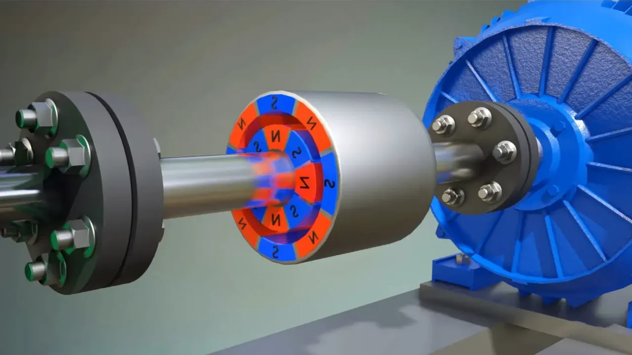
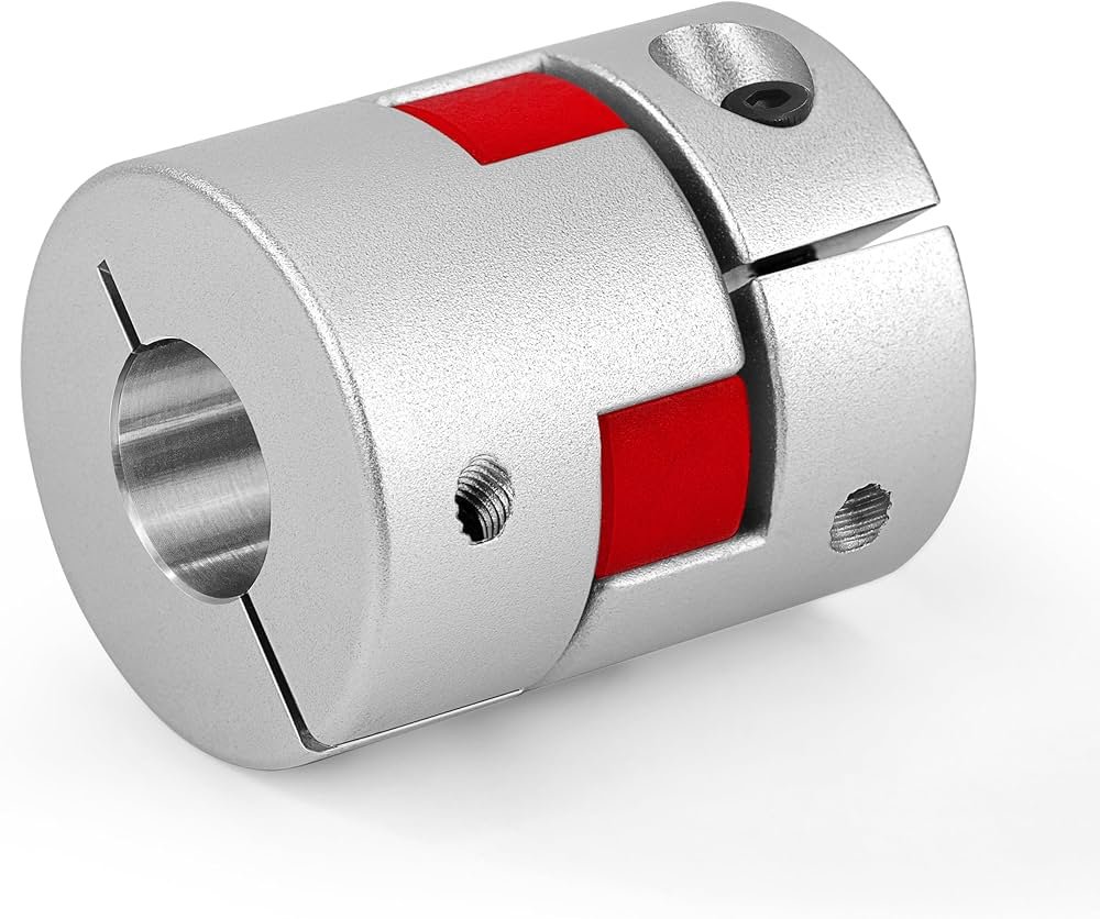
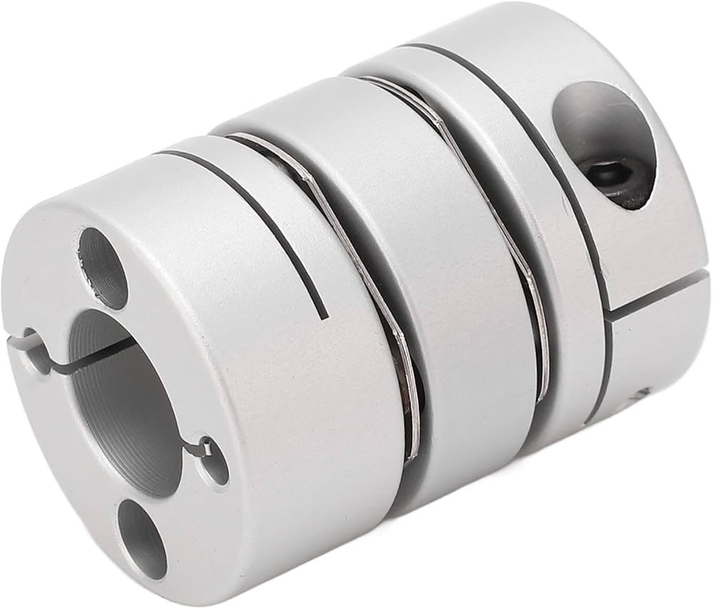
Rotating shafts rarely achieve perfect alignment during installation due to thermal growth. Metal membranes accommodate parallel, angular, and axial offsets simultaneously without wear. Excessive parallel misalignment creates high radial reaction forces on adjacent bearings. Angular misalignment causes bending stresses within the flexible metallic elements. Selecting a double-flex design provides significantly higher parallel offset capacity. Some operators initially consider a Flexible coupling elastomeric coupling for shock absorption. However, elastomeric materials degrade rapidly in hot or chemically aggressive environments. Stainless steel discs maintain structural integrity at high temperatures where elastomers fail completely. Precision alignment remains critical even when utilizing highly flexible metal connectors. Minimizing installation offsets directly extends the service life of all connected components. This proactive approach lowers maintenance expenses and boosts overall plant productivity.
| Series Size | Torque Limit (Nm) | Maximum Velocity (RPM) | Axial Displacement (mm) |
|---|---|---|---|
| Model 110 | 450 | 12,000 | 1.2 |
| Model 150 | 1,200 | 9,500 | 1.6 |
| Model 210 | 3,800 | 7,200 | 2.1 |
Analyzing Coupling Size and Performance Specifications
The performance data reveals a clear relationship between frame size and mechanical limits. Larger series accommodate significantly higher torque loads but operate at lower maximum speeds. For example, Model 210 handles three thousand eight hundred Newton-meters of force. However, its maximum safe operating speed decreases to seven thousand two hundred revolutions. Selecting a compact diaphragm coupling size optimizes high-speed turbine operations effectively. Smaller units feature lower rotational mass and reduced centrifugal forces. Designers must balance torque requirements against maximum operational speeds during selection. This careful evaluation prevents mechanical failure in high-speed applications. Engineers often consult these charts to match motor outputs with safe limits. Accurate parameter matching ensures the safety of the entire system. These metrics form the foundation of a successful power transmission layout.
Interpreting Operational Limits of Diaphragm Coupling Systems
Operating limits extend beyond simple rotational speed and torque boundaries. Dynamic axial displacement forces the metallic discs to stretch continuously during rotation. This continuous flexing generates internal heat within the individual pack assemblies. Excessive heat generation accelerates metal fatigue and reduces operational lifespan. Ambient environment conditions also influence the overall durability of metallic membranes. High temperatures reduce the fatigue limit of standard spring steel materials. Operators must evaluate temperature factors when specifying parts for hot areas. Corrosion represents another severe threat in chemical processing plants. Special coatings or stainless steel options mitigate these environmental hazards. Regular monitoring of operating temperatures prevents sudden component degradation. Plant reliability improves significantly when users respect these design constraints.
| Coupling Configuration | Angular Offset Limit (deg) | Parallel Offset Capacity (mm) | Torsional Stiffness Rating |
|---|---|---|---|
| Single Flex Design | 0.5 | 0.0 | Extremely High |
| Double Flex Spacer | 1.0 | 3.5 | Moderate to High |
Comparing Single and Double Flex Configurations
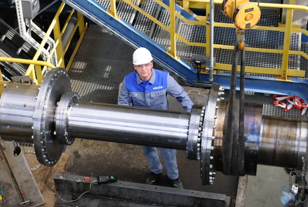
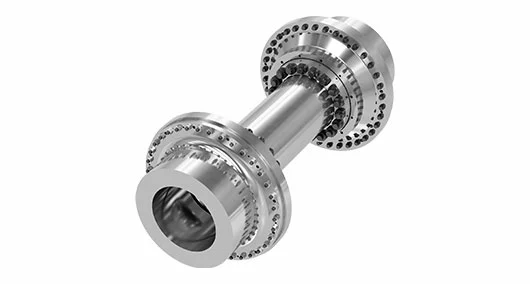
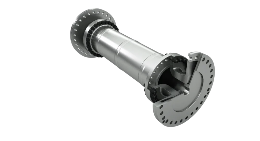
Selecting the appropriate configuration requires analyzing the physical layout of shafts. Single flex models contain only one disc pack between hubs. This layout handles angular misalignment but accommodates zero parallel offset. Machinery setups with parallel shaft separation require double flex spacer models. Spacers create two separate flex points to accommodate larger offset distances. Double flex versions allow up to three point five millimeters of offset. However, single flex units deliver superior torsional stiffness for precise positioning. Systems requiring high dynamic response benefit from single flex rigidity. Engineers select spacer lengths based on the distance between shaft ends. Proper model matching ensures smooth operation without placing stress on bearings. Standardizing configuration choices simplifies inventory management in large factories.
- AISI 301 Stainless Steel: Provides high fatigue strength and corrosion resistance.
- Pre-stretched Bolt Assemblies: Ensure consistent clamping force during dynamic loading.
- ISO 1940 G1.0 Balance Grade: Reduces vibration in high-speed applications.
- API 671 Standard Certification: Guarantees reliability for critical petroleum operations.
In-Depth Review of Metal Component Standards
Premium components rely on superior raw materials and strict testing protocols. High-grade stainless steel plates form the flexible core of each assembly. These metallic membranes must endure billions of flexing cycles during service. Special surface treatments prevent fretting corrosion between individual metal discs. High-strength bolts secure the entire diaphragm coupling to the rigid hubs. Precise tightening torque prevents bolt loosening under intense centrifugal forces. Balancing grades determine the level of residual vibration during operation. High-speed machinery demands strict compliance with ISO balance requirements. Meeting these strict standards prevents bearing wear and seal leakage. Procurement specialists verify these material certifications before placing orders. Investing in certified materials guarantees long-term safety in continuous operations.
Evaluating API 671 Specifications for Critical Machinery
Critical turbomachinery requires specialized hardware to ensure safety in hazardous zones. The American Petroleum Institute defines strict requirements under the API 671 standard. This standard demands fail-safe designs for high-power transmission systems. For example, systems must include guard catchers to contain flying parts. Selecting a shaft coupling torque coupling according to these criteria minimizes risk. Manufacturers perform non-destructive testing on all load-bearing components. Ultrasonic inspections detect microscopic flaws inside the solid steel hubs. These procedures protect personnel and expensive equipment from catastrophic failures. Petroleum refineries strictly enforce API compliance to meet environmental laws. Purchasing teams verify compliance documents during the procurement phase. Certified hardware delivers ultimate reliability for the most demanding plant operations.
Optimizing Torsional Stiffness and Operational Safety
Torsional stiffness determines how quickly a system responds to sudden load changes. High stiffness prevents angular lag between the driving and driven components. This responsiveness remains vital for synchronous motors and test benches. Metal membranes provide excellent torsional rigidity compared to elastomeric inserts. However, excessive stiffness can shift system resonance into the operating range. Engineers perform torsional vibration analysis to identify critical speed zones. Adjusting spacer weight or disk thickness alters the natural frequency safely. Dynamic balancing also minimizes centrifugal forces at high rotational speeds. Proper balance reduces bearing vibration and prevents premature seal leaks. Maintenance teams monitor vibration spectra to detect shaft alignment issues early. Proactive monitoring prevents major failures and ensures smooth industrial operations.
Maintaining Transmission Systems for Long Service Life
Scheduled inspections represent the best way to prevent unexpected transmission failures. Technicians must visually check the metallic components for signs of distress. Cracks in the outer plates indicate high fatigue stress from misalignment. Replacing a damaged metal connector quickly protects the connected expensive machinery. Operators check bolt tightness using calibrated torque wrenches during shutdowns. Corrosion checks are vital in coastal or highly acidic plant areas. Applying protective grease coatings shields metallic surfaces from atmospheric moisture. Well-maintained machinery operates at peak efficiency with minimal energy loss. Keeping detailed maintenance logs tracks component performance over many years. These records help engineering teams plan future system upgrades effectively. Proper care ensures continuous plant operations and maximizes equipment return.
FAQ
What are the main benefits of using a metallic membrane connector?
Metallic membrane connectors offer several advantages for demanding high-speed rotational applications. They operate without any lubrication because they do not contain moving parts. This feature eliminates routine maintenance and significantly reduces factory operational expenses. Furthermore, a high-quality diaphragm coupling provides excellent torsional stiffness for precise operations. These elements also tolerate moderate levels of misalignment without transferring high loads. Operators secure consistent performance even in aggressive chemical or high-temperature environments. The durable metal construction ensures a long service life under continuous loading. Such robust physical characteristics make them perfect for industrial turbine systems. Reliability remains unmatched when compared to traditional rubber or gear connectors.
How do environmental temperatures affect flexible disk systems?
High ambient temperatures directly influence the mechanical performance of steel disc elements. Extreme heat causes thermal expansion and alters shaft alignment metrics dynamically. This alignment shift increases the bending stresses on individual flexible metal plates. Standard carbon steels lose fatigue strength when operating in very hot environments. Engineers select special alloys like Inconel for applications exceeding two hundred degrees. These high-performance materials maintain elastic properties under severe thermal stresses. Conversely, freezing temperatures make standard steel components more brittle and vulnerable. Operators must specify low-temperature steel to prevent cracking during cold startups. Matching material limits with real working conditions ensures long-term operational success.
When should industrial operators replace transmission elements?
Maintenance crews must monitor critical indicators to determine optimal component replacement intervals. Visual inspections represent the easiest method to find initial signs of fatigue. Tiny cracks on disk surfaces require immediate attention to prevent total failure. Fretting corrosion between individual plate layers also indicates excessive shaft misalignment. Abnormal noise during startup indicates potential loose bolts within the hub assembly. Advanced plant operators use vibration sensors to track real-time machine health trends. Sudden increases in vibration amplitude suggest immediate system shutdown for detailed inspection. Replacing worn components proactively prevents expensive secondary damage to adjacent machinery. Regular monitoring schedules guarantee safe and reliable factory operations year after year.