Start With Geometry, Material, and Function
CNC machining minimum wall thickness depends on the wall’s height, unsupported span, material, and required accuracy. Published metal recommendations commonly start around 0.8 mm. Plastic recommendations often start around 1.5 mm. Some suppliers recommend thicker sections for economical production. Treat those values as design screening guidance and request a review of your geometry. A short supported rib behaves differently from a tall enclosure wall. The finished component must also withstand assembly loads, service conditions, and handling.
Compare CNC Machining Minimum Wall Thickness Recommendations
Published design guides use different manufacturing assumptions, so their figures need context. Separate general starting recommendations from thinner features requiring individual assessment. Review wall proportions and support alongside any thickness guideline. Thicker sections can improve machining stability and simplify workholding, helping control production costs. The table compares common starting points and their intended use. Confirm each value against the actual material, geometry, tolerance, and finishing requirements. Ask MXCZ to review the complete drawing and quantity before freezing the design.
Published design guidance for preliminary wall review
| Recommendation type | Published guidance | How to use it |
|---|---|---|
| General design starting point | Recommended 0.8 mm for metals and 1.5 mm for plastics. | Review geometry before adopting these starting values. |
| Thinner features requiring review | Potentially feasible 0.5 mm for metals and 1.0 mm for plastics. | Request individual feasibility assessment. |
| Approximate inch-based guideline | General guideline of 1/32 inch, approximately 0.794 mm. | Evaluate wall proportions, support, tolerance, and cost together. |
| Thicker starting recommendation | General starting recommendation of 0.060 inch, approximately 1.52 mm. | Assess height and span when considering thinner features. |
Separate Material Strength From Machining Stability
A strong alloy can still move under cutting forces when its section lacks stiffness. Material hardness alone cannot establish a practical wall dimension. Aluminum, stainless steel, and engineering plastics need different tooling and process choices. Plastics can deflect and respond strongly to machining heat. Metal stock can also move as material removal releases internal stresses. Consider the actual grade, stock condition, temperature, and required finish. MXCZ’s stainless steel precision machined parts provide relevant product examples. Confirm the chosen grade and drawing requirements for your component.
Review Height, Span, and End Support Together
Keep wall thickness, wall height, and unsupported length distinct in the drawing review. A long wall with a free upper edge can vibrate during finishing. Adding a rib, shortening the span, or connecting the ends can improve support. Check that these changes preserve access, weight limits, and mating clearances. Consider a wall measuring 20 mm high and 1 mm thick. Its height-to-thickness ratio is 20:1. That ratio flags a review need rather than proving manufacturability. Thin pocket floors need separate attention because their support and loading differ from vertical walls.
Protect the Finished Wall Through the Tolerance Stack
Nominal dimensions alone can hide an unacceptable remaining section. For a centered sleeve, wall thickness equals half the difference between outside and inside diameters. Consider an outside diameter of 20.00 ±0.05 mm. Pair it with a bore of 18.00 ±0.05 mm. The nominal wall measures 1.00 mm. Opposing size limits reduce the calculated wall to 0.95 mm. Bore offset can reduce the local wall further. Define relevant geometric controls and identify critical measurement locations. State whether acceptance applies after machining, heat treatment, or surface finishing. Check flatness and position independently from wall thickness.
Plan Cutting, Workholding, and Inspection as One Process
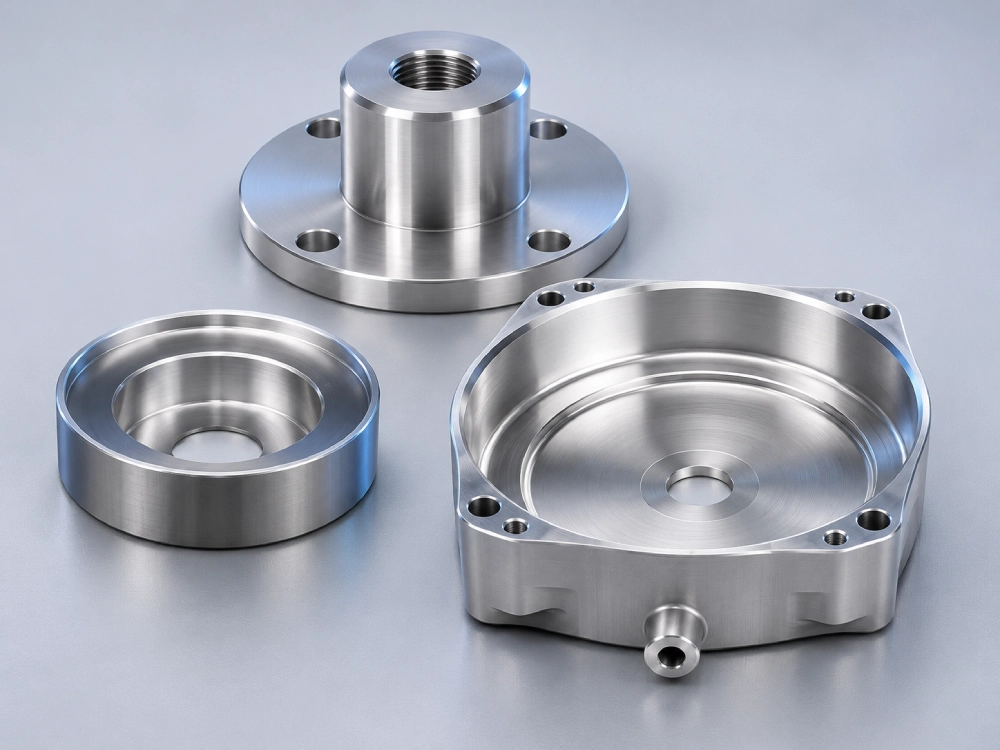
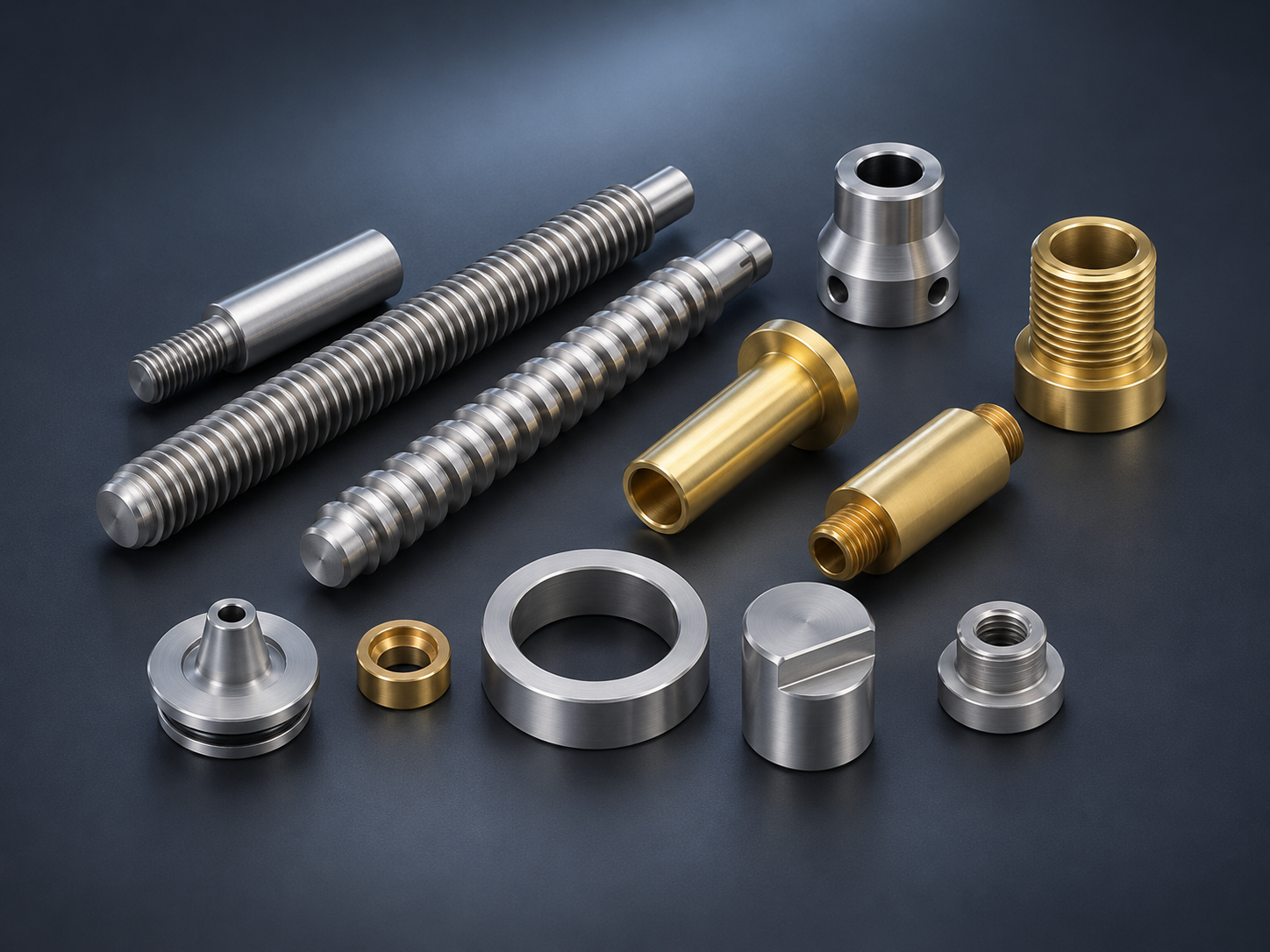
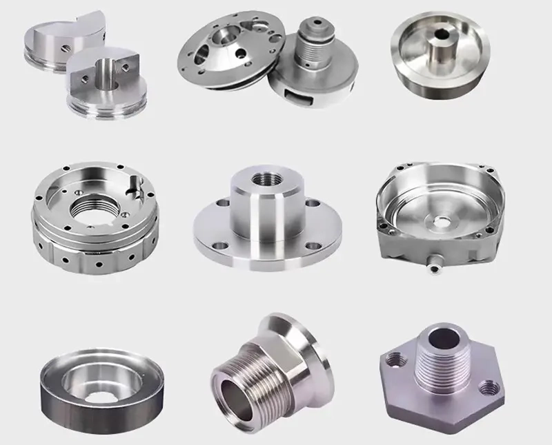
Thin features can deflect under both cutting and clamping forces. Ask the machinist how roughing, finishing, and fixture release affect the final shape. Support may help during cutting, but inspect the component in the specified final condition. A soft or slender wall can also move under a measurement probe. Agree on suitable contact force, support, and temperature conditions. MXCZ’s precision milled components offer a starting point for drawing-based discussions. Product photographs illustrate component types. A drawing review must establish the achievable wall, tolerance, and inspection method.
Confirm CNC Machining Minimum Wall Thickness Before Production
Send the supplier matching CAD and drawing revisions, material grade, quantity, finish, and critical wall locations. Explain why the thin section matters, including weight, flexibility, clearance, or thermal requirements. Identify features that engineering can change. Request a sample plan that checks thickness and shape after fixture release and final treatment. Define acceptance criteria before ordering the sample. Include assembly checks if fasteners, seals, or press fits load the wall. Use the following review sequence to resolve feasibility and acceptance requirements before production.
- Mark the thinnest local section and its tolerance limits.
- Record wall height, unsupported span, nearby holes, and end supports.
- Confirm grade, stock condition, final finish, and service loads.
- Request supplier feedback on tool access, workholding, and inspection.
- Agree on sample measurements and functional checks.
- Approve the verified drawing revision before releasing the production order.
Frequently Asked Questions
Is 0.5 mm wall thickness possible in CNC machining?
Some supplier guides describe 0.5 mm metal walls as potentially feasible after individual review. Success depends on geometry, material, support, tooling, and acceptance requirements. A short rib may need a different process from a tall enclosure wall with the same thickness. Ask the supplier to assess your exact model and critical dimensions. Provide the permitted design changes and expected quantity. Then verify a sample after unclamping and final treatment. Include the wall’s service loads in the engineering review, especially where assembly forces can distort it.
How should I measure a thin wall without deforming it?
Choose the method around accessibility, material stiffness, and the acceptance drawing. A micrometer can check accessible sections, but excessive measuring force can bend a flexible feature. Optical methods may help where the instrument can resolve both surfaces. Coordinate measurement can assess geometry, but probe force and access still matter. Specify the measurement locations and whether supports may contact the component. For a sleeve, diameter measurements alone may miss local thinning from an offset bore. Agree on the inspection method before production and compare it with the functional requirement.
When should I thicken the wall or change the manufacturing route?
Consider a design change when machining, finishing, inspection, or assembly repeatedly distorts the feature. First identify whether height, span, unsupported geometry, or overly tight tolerances drive the problem. A local rib or shorter pocket may preserve more of the original design than increasing every wall. For suitable enclosures, compare a fabricated sheet metal construction with a fully machined form. Include joining, sealing, tolerance, tooling, and batch quantity in that comparison. Ask the supplier to quote the approved alternatives against the same functional acceptance criteria.