Industrial Shaft Alignment and Common Coupling Misalignment Types
Rotating machinery relies on precise shaft positioning to maintain continuous production. Heavy industrial plants suffer severe equipment breakdowns when technicians overlook shaft positioning issues. Maintenance professionals must analyse various coupling misalignment types to protect mechanical components from sudden failure. Misaligned drivetrains transfer excessive forces across connected rotating elements. These destructive forces quickly destroy bearings and mechanical seals in high-speed applications. Plant operators achieve superior uptime by monitoring motor offsets regularly. Standard operating procedures require immediate correction when vibration levels exceed safe thresholds. Technicians use precision tools to ensure precise co-axial rotation during system setup. Early detection limits operational expenses while optimizing mechanical system efficiency over long operating periods. Facility managers prioritize scheduled diagnostic checks to protect critical assembly lines.
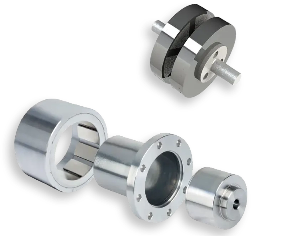
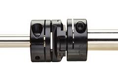
Analyzing Radial Offset in Rotating Machinery
Parallel offset occurs when two shaft axes remain parallel but do not share a single centerline. This specific deviation places tremendous radial stress on coupled industrial shafts. Engineers frequently select a stainless steel torque rating coupling to handle severe rotational forces. Such a robust component accommodates minor parallel errors while transmitting high torque. Excessive offset still accelerates metallic fatigue within the connection element. Rapid seal deterioration usually indicates that the radial displacement exceeds standard limit tolerances. Maintenance crews must reposition the driving machine to bring the shafts back into correct alignment. Adding precision metal shims under the motor feet corrects vertical elevation mismatches. Dial indicators yield highly accurate measurements during this critical alignment process. Proper corrective actions protect expensive internal machine parts from premature failure. Consistently achieving precise positioning reduces energy losses across the entire drivetrain.
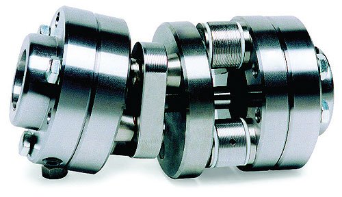
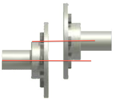
Angular Deviation and Its Impact on Mechanical Seals
Angular deviation happens when shafts intersect at an angle rather than forming a straight line. This angle impacts different coupling misalignment types by creating asymmetrical physical gaps between the flange faces. Continuous rotation under these conditions forces the flexible elements to bend back and forth repeatedly. Cyclic bending generates high internal friction which rapidly heats up elastomeric components. Elastomeric parts degrade quickly under high heat, leading to complete driveline disconnection. Technicians measure the gap difference at opposite sides of the coupling face to determine angularity. Modern laser alignment systems simplify this measurement by calculating the exact angle instantly. Correcting this angle requires precise sideways adjustments of the machine base. Implementing these corrections prevents structural vibration from damaging adjacent machinery components during operation. Regular monitoring verifies mechanical stability under full load conditions.
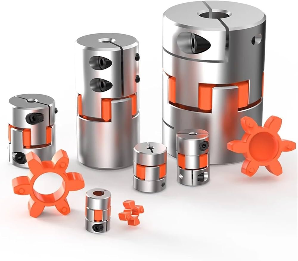
Axial Movement and Complex Axial Displacement Issues
Axial displacement involves the movement of shafts along their longitudinal axes. Thermal expansion represents the primary driver of this axial movement in high-temperature applications. A Flexible coupling elastomeric coupling can absorb moderate axial growth without transferring heavy thrust loads. These elastomeric inserts compress slightly to accommodate the moving shafts safely. Excessive axial force pushes the motor rotor out of its magnetic center. Mechanical damage occurs when the shaft shoulders contact the bearing housings directly. Plant engineers must calculate thermal growth rates before setting the initial cold gap. Utilizing correct spacing during installation prevents thrust bearings from overheating. Maintenance specialists monitor axial clearances to protect internal turbine stages from physical rubbing. Diligent monitoring ensures long-term operational safety across all industrial rotating machinery. Operations run smoothly when machinery maintains stable axial clearance profiles.
Comparing Key Coupling Misalignment Types for Maintenance
| Deviation Category | Physical Symptoms | Acceptable Tolerances |
|---|---|---|
| Radial Offset | High radial vibration, early bearing seal failure | Less than 0.05 millimeters |
| Angular Deviation | Axial vibration, metal fatigue in couplings | Less than 0.1 degrees |
| Axial Displacement | Thrust bearing wear, rotor center shifting | Within manufacturer specifications |
Analysis of Mechanical Coupling Tolerance Standards
Engineers reference precise specifications when assessing operational machinery performance metrics. The preceding comparative table highlights standard physical boundaries for normal machinery operation. Maintenance teams mitigate specific coupling misalignment types during routine shutdown periods [1]. Setting radial offset targets below critical limits extends bearing life significantly. Rigid components demand tighter tolerance thresholds than flexible elastomer alternatives. Operating machinery beyond these recommended tolerances causes severe damage to transmission shafts. Vibration analysis reveals mechanical issues before physical destruction occurs in the system. Technicians must document all alignment corrections to monitor component wear trends. Historical data helps predict future maintenance requirements for rotating machinery. Routine physical checks prevent costly unplanned downtime in industrial facilities. Documenting mechanical corrections creates a reliable system history for engineering reviews.
Operational Target Limits for Industrial Machinery Speeds
| Operating Speed (RPM) | Maximum Radial Limit (mm) | Maximum Angular Limit (mm/100mm) |
|---|---|---|
| 900 RPM | 0.08 mm | 0.07 mm |
| 1800 RPM | 0.05 mm | 0.05 mm |
| 3600 RPM | 0.03 mm | 0.03 mm |
Influence of Rotating Speed on Mechanical Clearances
Higher rotational speeds demand much stricter alignment limits to control destructive centrifugal forces. The data table outlines how allowable tolerances decrease sharply as motor speeds increase. Operating personnel must recognize these mechanical parameters to prevent excessive vibrations in high-speed systems. Failure to meet these stringent limits leads to rapid bearing housing degradation. Unbalanced forces generate high temperatures inside the lubrication systems, destroying grease quality. Plant engineers always consult original manufacturer specifications before starting any precision machine calibration. Regular alignment testing ensures that heavy machinery stays within safe operational parameters. Keeping precise records of these boundaries helps maintenance crews identify structural issues early. This proactive management strategy extends machinery life and minimizes overall operational expenses. Reliable rotating equipment operates quietly when crews maintain strict alignment targets.
Industrial Tools for Shaft Deviation Measurement
Laser shaft alignment systems with dual sensor heads
Dial indicators featuring precision magnetic bases
Feeler gauges used with straightedges for rapid checks
Calibrated shims for precise vertical machine adjustments
Mechanical gap gauges for measuring flange distance
Evaluating Precision Alignment Instruments and Calibration Methods
Each listed maintenance instrument serves a vital purpose in detecting all coupling misalignment types in the field. Selecting the proper hardware depends on mechanical tolerance requirements and available physical space. Laser alignment systems offer high precision by displaying real-time corrective data on digital screens. Dial indicators provide reliable mechanical measurements without relying on battery power or electronic systems. Experienced operators combine multiple methods to verify measurement accuracy during critical installation phases.
FAQ
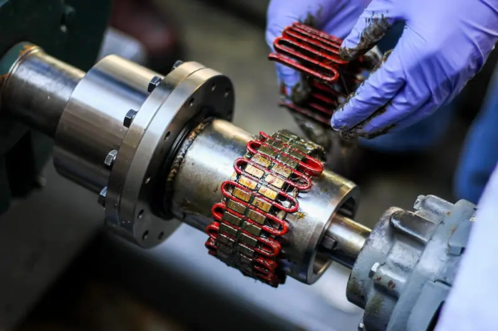
How does angular offset damage flexible grid elements?
Severe angular offset affects various coupling misalignment types because it creates uneven loading patterns on grid teeth. This uneven load distribution concentrates rotational stress on isolated areas of the flexible grid. Metal fatigue develops rapidly when the grid flexes continuously beyond its designed physical limits. Lubricant squeeze-out occurs due to high localized pressures during high-speed rotating operations. Dry metal-to-metal contact accelerates abrasive wear and leads to grid breakage inside the housing. Maintenance technicians notice fine metal shavings during inspections when grid wear becomes severe. Replacing damaged components promptly prevents complete drivetrain failure and protects adjacent motor bearings. Regular lubrication helps mitigate moderate wear during normal operating cycles. Proactive inspection schedules reduce unexpected repair costs significantly.
Why does thermal growth cause machinery shaft deviation?
Machinery components expand dynamically as operating temperatures rise during heavy production cycles. This thermal expansion shifts the shaft centerlines away from their cold installation positions. Different metals expand at unequal rates, creating significant vertical and horizontal elevation changes. Motor frames usually remain cooler than hot pump casings, causing unequal relative movement. Technicians must calculate expected thermal growth to set correct offsets during cold alignment. Neglecting these calculations results in severe vibration once the system reaches operating temperature. Laser alignment tools simulate target offsets to simplify these complex thermal adjustments. Proper cold compensation ensures perfect collinear rotation during actual peak load operations. Plant reliability increases when maintenance crews account for thermal growth variables. Dedicated software tools predict temperature rises to assist technicians in planning setups.
What are the symptoms of severe coupling failure?
Severe coupling degradation shows clear physical symptoms before complete mechanical breakdown occurs. Abnormal high-frequency vibration represents the most common indicator of a failing connection. Excessive noise from the coupling guard suggests physical contact or loose internal components. Maintenance crews often detect high heat radiating directly from the coupling housing during inspections. Elastomeric debris under the machine base indicates rapid insert degradation in flexible setups. Loose foundation bolts frequently result from continuous structural vibration caused by misalignment. Plant operators must shut down machinery immediately when these symptoms appear during production. Conducting physical inspections prevents catastrophic structural damage to expensive driven equipment. Regular diagnostic monitoring protects capital assets from premature mechanical failure. Implementing scheduled maintenance cycles prevents unexpected operational stops.