Introduction to Gd&T Symbols CNC in Modern Manufacturing
Gd&T symbols CNC define geometric tolerances used in precision machining environments. Engineers apply these symbols to control shape, orientation, and location. Clear definitions help avoid ambiguity during production processes. Manufacturers rely on standardized tolerancing to ensure part consistency. Complex assemblies require accurate feature relationships to function correctly. Traditional dimensions cannot fully describe these requirements. Global industries use geometric tolerancing to maintain quality standards. Aerospace and automotive sectors demand strict tolerance control. Consistent communication between teams improves production efficiency. This system supports scalable manufacturing across international supply chains.
Importance of Gd&T Symbols CNC in Precision Engineering
Precision engineering requires strict control over part geometry and variation limits. Gd&T symbols CNC ensure that components meet functional and assembly requirements. Poor tolerancing often causes misalignment or mechanical failure.
Engineers define allowable variation using standardized symbols and datums. Clear tolerances reduce rework and minimize production waste. Consistent specifications improve interchangeability between components. Manufacturing teams maintain accuracy across large production batches. Inspection processes become more reliable with defined criteria. Standards such as ASME Y14.5 guide proper application. Companies adopting these standards achieve better product reliability and consistency.
Core Categories of Geometric Tolerances in CNC Machining
Gd&T symbols CNC are divided into several functional categories. Each category controls a specific aspect of geometry. Form tolerances manage flatness, straightness, and circularity. Orientation tolerances define angular relationships between features. Location tolerances specify feature placement using datum references. Profile tolerances control complex surface variations. Runout tolerances measure rotational accuracy of components. Each category directly affects machining strategies and tooling selection. Operators must interpret these categories correctly during production. Clear classification simplifies communication and improves machining efficiency.
Table: Major Gd&T Categories and Their Functions
| Category | Function | Application |
|---|---|---|
| Form | Controls shape accuracy | Flat surfaces and cylinders |
| Orientation | Defines angular relationships | Perpendicular features |
| Location | Specifies feature position | Hole alignment |
| Profile | Controls complex surfaces | Aerospace parts |
| Runout | Measures rotational deviation | Shaft components |
Each tolerance category affects machining precision in different ways. Form controls keep surfaces within strict shape limits. Orientation controls preserve correct angular relationships during assembly. Location tolerances ensure accurate positioning relative to datums. Profile tolerances manage complex curved geometries effectively. Runout controls maintain stable rotation in mechanical systems. Clear knowledge of these functions improves machining accuracy and inspection consistency.
Interpreting Gd&T Symbols CNC in Engineering Drawings
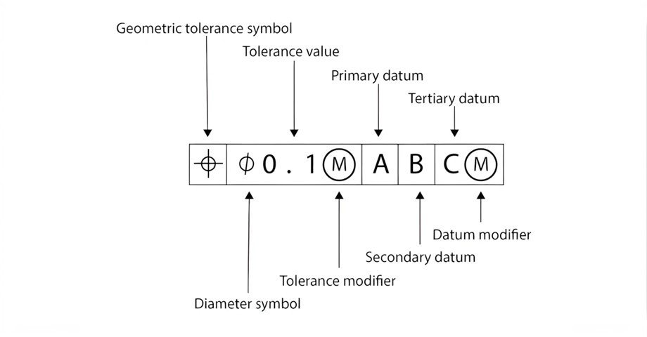
Engineers rely on technical drawings to interpret Gd&T symbols CNC accurately. Feature control frames define tolerance type, value, and references. Datums act as primary measurement points for alignment. Proper datum selection ensures consistent inspection results. Symbols are placed near controlled features on drawings.
Clear placement reduces the risk of misinterpretation. Operators follow these instructions during machining processes. CAD systems integrate tolerancing directly into digital models. Digital workflows improve collaboration between design and manufacturing teams. Accurate interpretation supports high-quality production outcomes.
Elements of Feature Control Frames
| Element | Description | Purpose |
|---|---|---|
| Symbol | Type of tolerance | Defines control method |
| Tolerance Value | Allowed variation | Sets precision limits |
| Datum Reference | Reference feature | Ensures alignment |
| Modifiers | Additional conditions | Refines tolerance rules |
Feature control frames create structured communication for tolerances in machining drawings. Each element defines specific geometric requirements for production. The symbol indicates the type of control applied. Tolerance values set acceptable variation limits for features. Datum references provide consistent measurement points. Modifiers refine tolerance conditions for real manufacturing scenarios. Engineers rely on these elements to prevent production errors. Precise interpretation supports compliance with design intent and quality standards.
Common Gd&T Symbols CNC and Their Applications
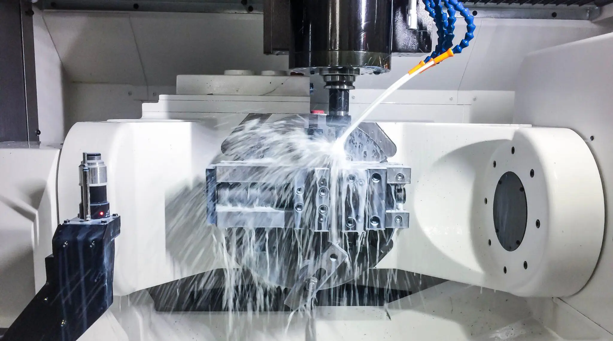
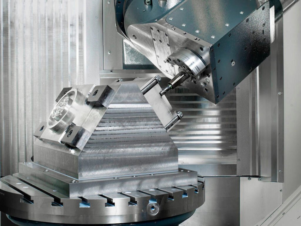
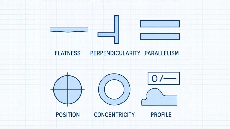
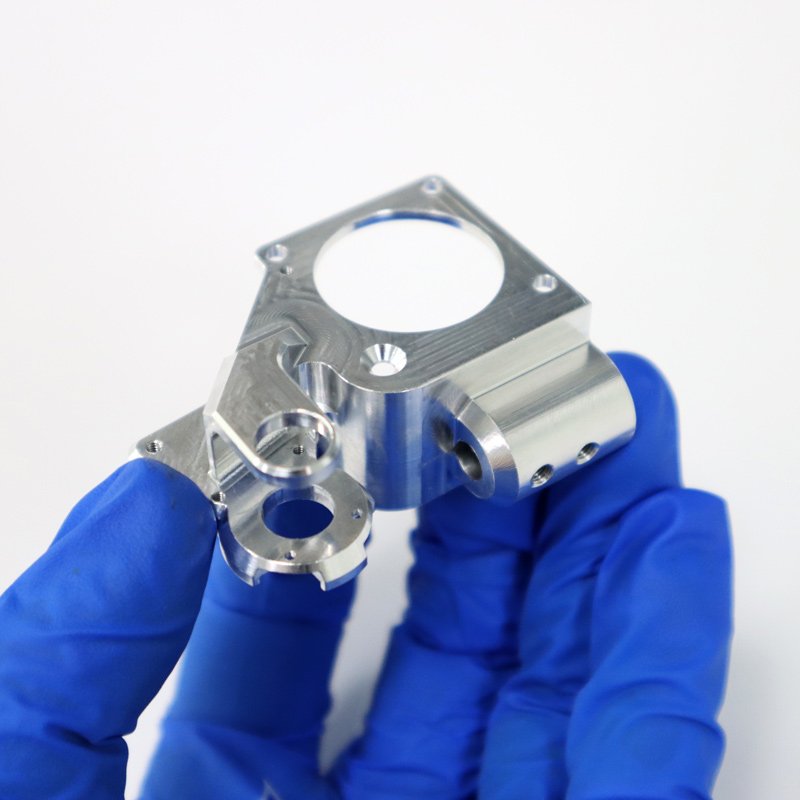
Gd&T symbols CNC appear frequently in machining operations across industries. Flatness ensures surfaces remain even during assembly. Perpendicularity controls angular alignment between intersecting features. Position tolerance defines precise feature placement. Concentricity ensures proper alignment in rotating components. Profile tolerances control complex shapes in advanced designs. These symbols guide machining strategies in milling and turning processes. For example, precision milled components require strict flatness and position control. Correct application improves toolpath accuracy and reduces machining errors. Engineers select symbols based on functional requirements and manufacturing constraints.
Common Symbols and Practical Uses
| Symbol | Name | Use Case |
|---|---|---|
| ⏥ | Flatness | Surface leveling |
| ⟂ | Perpendicularity | Right angle features |
| ⌖ | Position | Hole placement |
| ◎ | Concentricity | Shaft alignment |
| ⌒ | Profile | Complex contours |
These symbols define essential requirements for machining accuracy and performance. Flatness ensures stable contact surfaces during assembly. Perpendicularity maintains structural integrity in joints. Position tolerance guarantees correct feature placement. Concentricity supports smooth rotation in mechanical systems. Profile control is vital for aerodynamic or ergonomic designs. Proper symbol usage improves manufacturability and product performance.
Benefits of Applying Gd&T Symbols CNC in Production
Gd&T symbols CNC provide significant advantages in manufacturing environments. Clear tolerancing reduces miscommunication between teams. Production errors decrease when specifications are well defined. Consistent quality improves product reliability and customer satisfaction. Standardization supports global manufacturing collaboration.
Engineers can optimize designs for both function and manufacturability. Reduced scrap rates lead to cost savings. Inspection processes become more efficient with clear criteria. High-precision industries benefit from improved consistency and repeatability.
Comparison Between Traditional Tolerancing and Geometric Tolerancing
Traditional tolerancing focuses on size and linear dimensions only. Gd&T symbols CNC provide a more advanced method for controlling geometry. They define relationships between features rather than isolated dimensions. Complex parts benefit from this integrated approach. Traditional methods often create unnecessary constraints. Geometric tolerancing allows more flexibility while maintaining function. Engineers can optimize designs without increasing manufacturing costs. This method improves both efficiency and product performance. Modern industries increasingly adopt geometric tolerancing systems.
Best Practices for Using Gd&T Symbols CNC
- Select datums based on functional requirements
- Avoid excessive tolerance constraints
- Follow ASME Y14.5 or ISO standards
- Ensure clear symbol placement on drawings
- Use CAD tools for accurate definition
- Train teams on correct interpretation
These practices improve the effectiveness of Gd&T symbols CNC in production. Proper datum selection ensures consistent measurement references. Avoiding excessive constraints simplifies machining processes. Standard compliance enhances global communication between teams. Clear symbol placement prevents interpretation errors. CAD tools improve design accuracy and efficiency. Continuous training strengthens technical capability across organizations.
Quality Assurance Improvements with Gd&T Symbols CNC
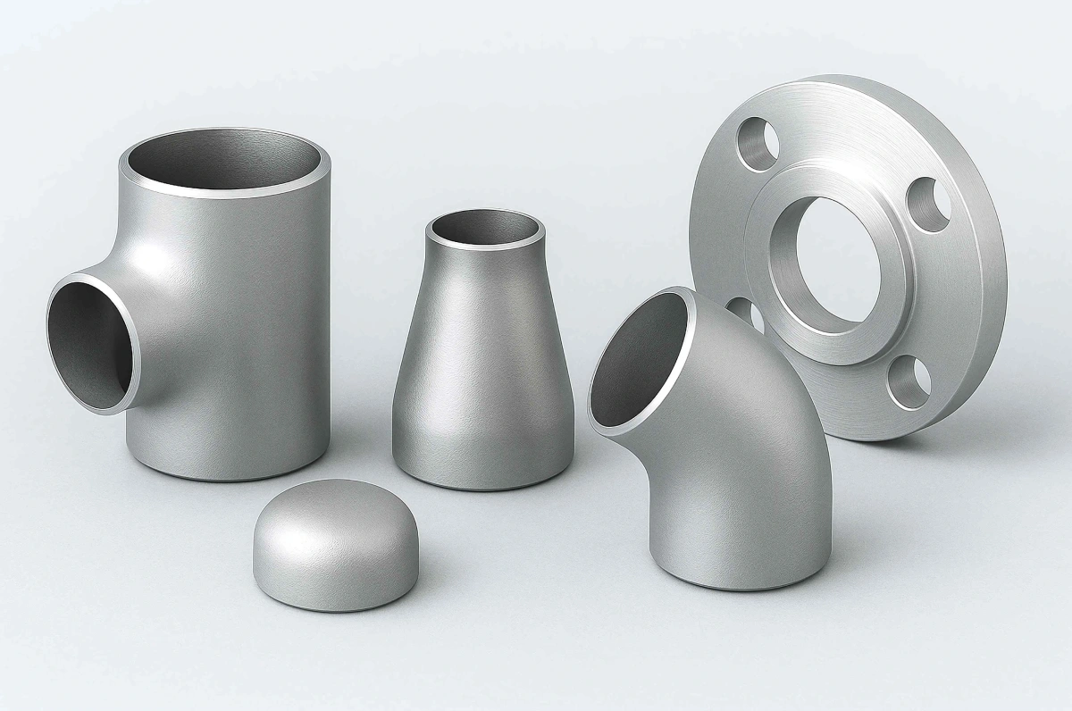
Quality assurance processes depend heavily on Gd&T symbols CNC for inspection accuracy. These symbols define measurable criteria for evaluating parts. Inspection tools such as CMM systems rely on these definitions. Clear tolerances reduce subjectivity during quality checks. Manufacturers can track deviations more effectively. Documentation becomes consistent across production batches.High-precision industries require strict compliance with tolerance standards. Stainless steel precision machined parts often demand tight geometric control. Accurate tolerancing ensures these requirements are consistently achieved. Improved QA processes enhance product reliability and performance.
Challenges in Implementing Gd&T Symbols CNC
Gd&T symbols CNC require proper training and experience for effective use. Misinterpretation can lead to production errors or delays. Software integration may require additional investment and setup. Complex designs increase the difficulty of tolerance definition. Engineers must balance precision with manufacturability carefully. Overuse of symbols can complicate drawings unnecessarily. Clear communication between teams remains essential. Companies must invest in training and tools to succeed. Proper implementation ensures long-term efficiency and quality improvements.
FAQ
What are the most important Gd&T symbols in CNC machining?
Several symbols control critical aspects of machining accuracy and functionality. Flatness ensures even surfaces for proper assembly contact. Perpendicularity controls angular relationships between intersecting features. Position tolerance defines exact locations for holes and slots. Concentricity ensures alignment in rotating components. Profile tolerances control complex surface shapes in advanced designs. Each symbol serves a unique engineering purpose. Engineers select symbols based on function and assembly requirements. Proper application improves both machining precision and inspection accuracy. Consistent use across projects enhances communication and reduces production risks.
How do Gd&T symbols CNC affect production cost?
Gd&T symbols CNC influence production cost through efficiency and precision control. Clear tolerances reduce errors and minimize material waste. Effective communication prevents misunderstandings between teams. Optimized tolerances avoid unnecessary machining complexity. Reduced scrap rates lead to long-term cost savings. However, overly tight tolerances can increase machining time and expenses. Engineers must balance precision with manufacturability carefully. Proper tolerancing improves workflow efficiency and reduces delays. Quality control processes also become more streamlined. These benefits contribute to lower overall production costs and improved consistency.
Why do manufacturers prefer Gd&T over traditional tolerances?
Manufacturers prefer Gd&T symbols CNC because they provide advanced geometry control. Traditional tolerances focus only on size, which limits accuracy. Geometric tolerancing defines relationships between features clearly. This approach supports complex designs and functional requirements. Clear definitions reduce ambiguity in technical drawings. Communication between teams becomes more efficient. Inspection processes gain reliability through defined criteria. Modern industries require higher precision and consistency. These advantages support widespread adoption across manufacturing sectors.