Evaluating Flexible Coupling Vs Rigid Coupling in Heavy Industries
Mechanical power transmission systems require precise component selection to ensure operational efficiency. Engineers frequently debate the merits of flexible coupling vs rigid coupling designs for critical machinery. Rigid devices establish a solid, unyielding connection between collinear shafts. They transmit maximum torque without any rotational backlash or angular deviation. Conversely, flexible configurations allow minor parallel or axial offsets. These designs protect sensitive motor bearings from premature wear and stress. Each category serves highly specific mechanical roles in demanding industrial setups. Selecting the incorrect coupling type often leads to catastrophic equipment damage. System designers must carefully analyze structural alignment, rotational speeds, and torque dynamics. This thorough assessment ensures optimal power transfer across the factory. Careful selection prevents expensive operational downtime and frequent repairs.
Exploring the Structural Design of Torsionally Stiff Components
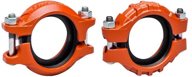
Rigid connectors feature a solid body that prevents any relative movement between shafts. Manufacturers often produce these parts from heavy carbon steel or robust stainless steel alloys. They secure the shafts using precise keyways, set screws, or clamp collars. One-piece sleeve designs slide over the shaft ends to provide seamless torque transmission. Alternatively, split-muff configurations clamp around the shafts to allow easier installation. Flanged designs connect separate components together with high-tensile bolts for heavy-duty applications. These rigid components offer extreme torsional stiffness under immense rotational loads. Such units perform exceptionally well in applications requiring exact timing and precise positioning. However, even minor shaft misalignment will generate severe stress on connected bearings. This intense load can cause rapid bearing failure and shaft breakage.
Mechanical Attributes of Elastomeric and Metallic Insert Systems
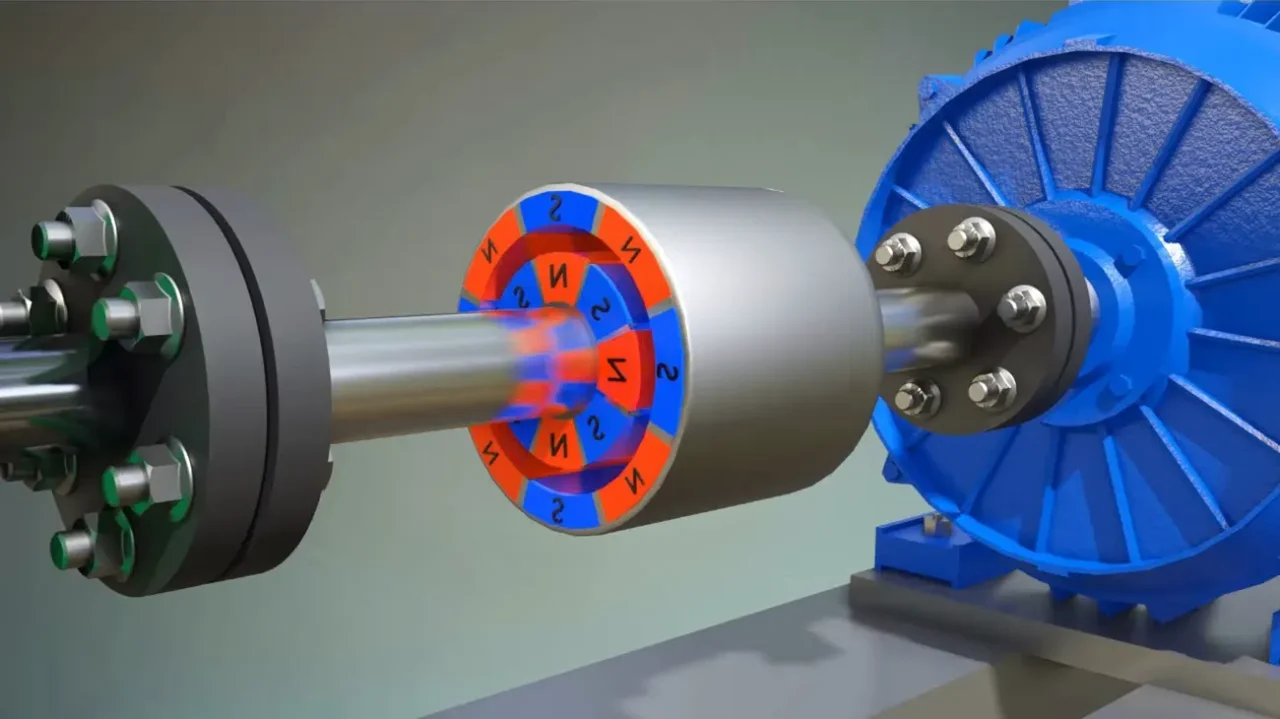
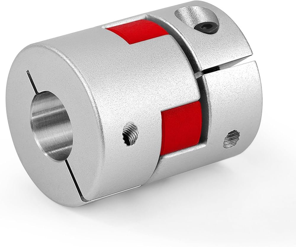
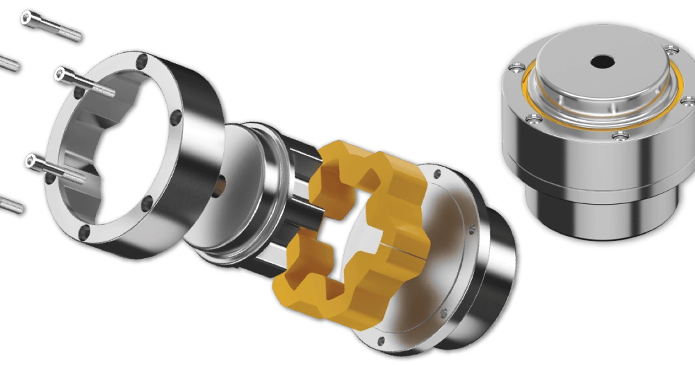
Flexible connectors incorporate resilient materials to accommodate slight shaft misalignments during operation. These designs utilize flexible elastomeric spiders or metal discs to absorb operational shocks. For example, jaw couplings employ polyurethane inserts to dampen high-frequency system vibrations. Metallic disc couplings use thin stainless steel sheets to handle angular offsets. Gear couplings rely on crowned teeth to permit axial sliding under heavy loads. Such elements allow the system to tolerate parallel, angular, or axial displacement. By isolating vibration, they protect fragile motors and downstream machinery from shock damage. Elastomeric inserts sacrifice some torsional stiffness to protect other expensive driveline parts. This compromise remains essential in systems with inevitable thermal expansion or structural movement. Reliable operation depends on choosing the correct insert material for environmental conditions.
| Parameters | Flexible Coupling | Rigid Coupling |
|---|---|---|
| Misalignment Tolerance | Up to 2 degrees angular | Zero tolerance |
| Vibration Dampening | High (elastomer spiders) | None (direct transfer) |
| Torsional Stiffness | Moderate to high | Extreme (infinite) |
| Maintenance Needs | Periodic insert replacement | Virtually maintenance-free |
Interpretation of Performance Metrics
The technical comparison highlights the distinct physical limits of each connecting device. Flexible designs prioritize protection by introducing compliant media to absorb misalignment stresses. Rigid units maximize torsional rigidity to ensure perfect synchronization between driving and driven equipment. This rigidity means the system transmits raw power without dampening torsional vibrations. Consequently, any bearing misalignments transfer directly through the metal body of the connector. Such direct load paths increase the risks of fatigue in adjacent rotating elements. Engineers must calculate the expected misalignment before choosing between these styles. Highly precise systems with perfect structural foundations usually benefit from solid connections. Conversely, misaligned or high-vibration systems require flexible intermediate components. Making the correct choice prevents unexpected mechanical failures during operation.
Key Mechanical Differences in Flexible Coupling Vs Rigid Coupling Setups
Industrial operations demand deep analysis of flexible coupling vs rigid coupling installations. Rigid connections require nearly perfect shaft alignment during initial setup. Even slight deviations generate immense radial loads on motor and pump bearings. These forces accelerate wear and reduce the lifespan of rotating machinery. In contrast, flexible options accommodate minor physical shifts during standard operations. They utilize polymer inserts to isolate damaging structural vibration.
Shaft alignment tolerance: checking parallel, angular, and axial offsets.
Environmental temperature: selecting elastomer spiders that withstand ambient heat.
Rotational velocity: balancing high-speed components to reduce centrifugal force.
Operational torque loads: calculating peak and continuous transmission forces.
Application Parameter Details
System designers must examine several key variables before finalizing any hardware purchase. Operating temperature represents a critical factor because elastomeric inserts degrade under high thermal stress. Extreme heat softens standard polyurethane spiders, which reduces their overall torque capacities. Conversely, freezing temperatures make polymer elements brittle and susceptible to sudden fractures. Rotational velocity also determines whether a system requires dynamically balanced components. High-speed shafts demand rigid structures or perfectly centered disc packs to prevent intense vibration. Operational torque characteristics require careful calculations of peak start-up loads. Selecting a connector based only on average running torque often causes premature shearing. These factors illustrate why comprehensive application evaluation remains necessary for machinery reliability. This analytical approach protects rotating elements from expensive mechanical failures.
Critical Operational Factors and Environmental Influences
Harsh industrial environments present unique challenges that affect flexible coupling vs rigid coupling setups. Corrosive chemicals, moisture, and abrasive dust can quickly degrade low-grade coupling metals. For instance, acid exposure destroys standard carbon steel flanges on solid connectors. Similarly, corrosive environments break down elastomer elements in jaw-style components. Designers must choose corrosion-resistant materials like stainless steel or specialized coated alloys. Additionally, high torque spikes can shear keys or damage internal gear teeth. Torsional windup in flexible elements can also introduce timing errors in automated lines. Solid components eliminate this timing issue but transmit all shock loads directly. Engineers must balance these environmental and physical limits during the development phase. Proper material selection guarantees long-term durability in severe environments.
Structural Resilience of Metal Connections under High Stress
Industrial machinery operating under extreme loads requires components with exceptional structural resilience. Heavy-duty mixers and high-pressure pumps depend on robust steel connectors to handle peak stresses. A stainless steel torque rating coupling offers superior strength in highly corrosive processing plants. These specialized connectors resist oxidation while transferring immense rotational power without structural deflection. They feature precise keyways and hardened clamp bolts to eliminate shaft slippage. Conversely, standard carbon steel connectors require protective coatings to survive humid environments. Such solid metal units maintain exact shaft positions under severe reversing loads. Rigid options completely eliminate the mechanical backlash that often degrades flexible polymer alternatives. Engineers select these rigid metal connectors to ensure uninterrupted power transmission. This robust design guarantees consistent performance in demanding physical operations.
| Feature | Flexible Connectors | Rigid Connectors |
|---|---|---|
| Wear Components | Elastomer spiders, metallic discs | None |
| Lubrication Required | Only for gear/grid types | None |
| Typical Lifespan | 2 to 5 years (elastomers) | Over 10 years (with alignment) |
| Balance Standards | AGMA Class 9 or ISO 1940 | AGMA Class 8 or ISO 1940 |
Maintenance Protocols and Dynamic Balance Standards
The maintenance data highlights the operational responsibilities associated with flexible coupling vs rigid coupling systems. Solid metal connectors require very little physical attention after precise installation. They eliminate the costs of purchasing replacement elastomeric elements over the system lifespan. However, technicians must verify shaft alignment regularly to prevent housing stress. Conversely, flexible components need periodic inspections to check for polymer degradation. Elastomer inserts suffer from wear caused by ozone, heat, and cyclic fatigue. Technicians must replace these wear elements before complete material shear occurs. Dynamic balancing remains critical for both designs at high rotational speeds. Adhering to AGMA Class 9 standards prevents excessive housing vibration. Proper maintenance schedules ensure long-term reliability and protect driving machinery.
Financial Implications and Component Replacement Cycles
Evaluating total ownership costs reveals the economic differences of flexible coupling vs rigid coupling choices. Solid components represent a lower initial capital expense for standard operations. They require zero ongoing spending on consumable parts like elastomeric spiders. However, their strict alignment needs can increase initial installation labor costs. Selecting a shaft coupling torque coupling ensures reliable transmission in high-speed applications. This specialized component prevents expensive shafts from slipping under sudden load spikes. In contrast, flexible options require higher initial investments but reduce bearing replacement costs. These elements absorb misalignment stresses that would otherwise damage expensive motor windings. Managers must evaluate installation labor, spare parts inventory, and potential downtime costs. Such balanced financial reviews ensure optimal budget allocation for plant operations.
Ultimate Recommendation for Modern Power Transmission
Making the final engineering decision requires matching system needs to component capabilities. High-precision machinery with perfect mounting structures benefits most from solid metal designs. These connectors maximize torsional rigidity and eliminate any rotational positioning errors. Conversely, systems subject to structural movement or thermal expansion require flexible components. Such resilient elements protect expensive bearings and motor shafts from catastrophic fatigue. Engineers must analyze torque ratings, speed requirements, and environmental factors beforehand. Proper selection avoids excessive maintenance costs and prevents unexpected plant shutdown. Investing in high-quality components ensures long-term reliability and efficient power transmission. This analytical process guarantees the longevity of both connections and connected machinery. Careful evaluation of structural limitations helps maintain peak efficiency throughout the system lifetime.
FAQ
Can rigid designs accommodate shaft misalignment?
Solid connectors have zero tolerance for parallel, angular, or axial displacement. Installing these parts requires highly precise shaft alignment using advanced laser tools. Even tiny deviations generate massive radial forces on connected shafts and bearings. These high loads cause rapid bearing wear and severe shaft fatigue. Consequently, utilizing solid connectors in misaligned setups results in catastrophic mechanical failures. Engineers must ensure perfect collinearity before clamping these rigid elements in place. Therefore, applications with inevitable structural shift or thermal expansion must avoid solid connections. Choosing flexible designs instead protects the entire motorized system from premature damage.
What are the primary failure mechanisms of elastic connectors?
Elastic connectors fail primarily due to material degradation of their internal components. High operating temperatures soften polymer spiders, which causes rapid deformation under load. Conversely, extreme cold makes these elastomeric elements brittle and prone to cracking. Excessive shaft offset also forces the insert to flex beyond its limits. This continuous stress generates heat inside the polymer, leading to physical breakdown. Additionally, harsh chemicals or UV exposure can rapidly decompose elastomeric materials over time. Technicians should inspect these elements regularly to identify wear signs like micro-cracks. Replacing worn inserts during planned outages prevents sudden driveline failures.
How do torque transmission limits compare between designs?
Solid configurations transmit much higher torque than elastic setups of identical size. They feature solid steel bodies that establish unyielding physical connections between shafts. This structural integrity allows rigid options to handle extreme starting torques and shock loads. Conversely, elastic designs rely on weaker polymer spiders or thin metal discs. Such materials limit the overall torque capacity to prevent shearing under stress. High torsional shock can destroy elastomer elements if the load exceeds ratings. Consequently, heavy-duty industrial drives require solid connections to transfer raw rotational force. Choosing the correct capacity prevents unexpected breakage during high-load operations.