The Technical Role of an Industrial Coupling
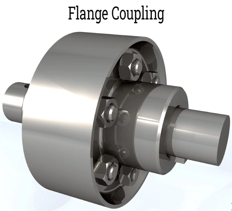
Heavy machinery systems require reliable power transmission components to operate efficiently. An industrial coupling connects two rotating shafts to transmit torque smoothly. Proper power transmission reduces vibration and protects expensive system motors from sudden shocks. Mechanical engineers choose these components based on shaft sizes and rotational speeds. Misalignment between motor shafts and driven equipment can cause catastrophic failure without this part. Rigid designs offer high torque density but lack flexibility. Flexible alternatives compensate for parallel or angular shaft errors during operation. Operators must inspect these parts regularly to prevent unplanned factory downtime. Selecting the correct component guarantees long-term durability for the entire drive train. Plants maximize production output by installing high-quality connection parts. Industrial facilities achieve better energy efficiency when shafts align precisely.
Torque Transmission Dynamics in Power Systems
Motor systems generate rotational force that must move to the output machine. Designers measure this rotational force as mechanical torque. A stainless steel torque rating coupling handles high loads in harsh chemical environments. Corrosion resistance makes stainless steel ideal for food processing and marine applications. Incorrect torque calculations often lead to sheared keys and fractured components. Safety factors of two or three protect the machinery from peak torque spikes. Technicians verify torque ratings before selecting a specific connector for their pump systems. Elastomeric inserts absorb shock loads and prevent damage to metal gears. Torsional stiffness determines how quickly the system responds to starting forces. High torsional stiffness ensures precise positioning in automated assembly lines. Engineers prioritize fatigue resistance when selecting metal membranes for continuous duty.
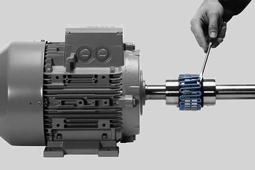
Essential Functions of Grid and Gear Components
Metal grid designs feature a serpentine spring that slots into grooved hubs. This spring deflects under load to spread shock impact across the mechanism. Gear configurations use crowned teeth to allow angular misalignment up to one degree. High torque density makes gear units suitable for heavy machinery connections. Regular lubrication keeps the moving metal teeth from wearing down prematurely. Steel mills rely on gear connectors for backup rollers and main drive lines. Synthetic grease offers superior protection under high centrifugal forces. Specialized seals retain the lubricant and exclude dust from the internal mesh. Failure to grease these assemblies results in rapid wear and noisy operation. Maintenance crews schedule inspections during planned plant shutdowns to avoid disruptions. Sturdy grid springs last for years when operators follow proper service intervals.
Structural Classification of Flexible Machinery Connectors
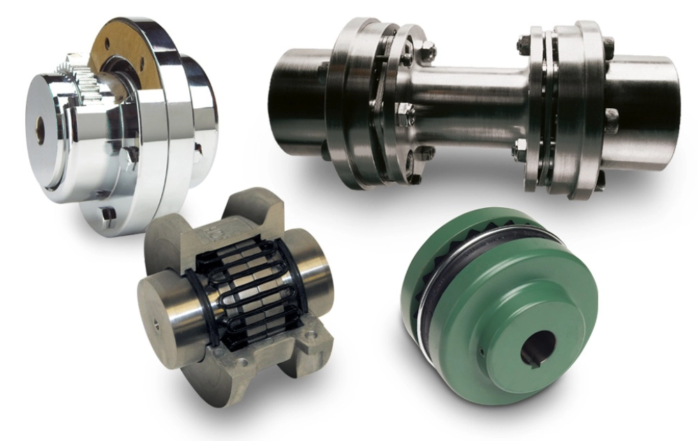
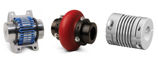
Industrial plants employ various mechanical designs to connect rotating shafts across different environments. Selecting the proper configuration depends entirely on specific application demands. Each design offers unique benefits regarding misalignment handling and torque capacity. Manufacturers separate these devices into main categories based on their internal materials. The following list highlights four common mechanical configurations found in modern factories.
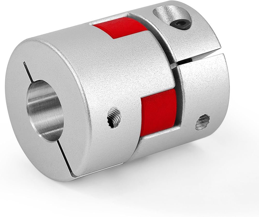
Jaw connectors: Use elastomeric spiders to cushion torque loads.
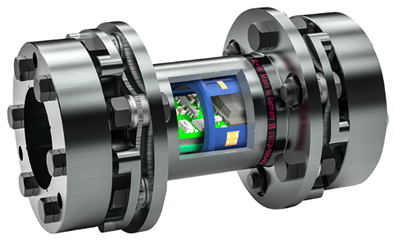
Disc connectors: Utilize thin metal sheets to accommodate misalignment.
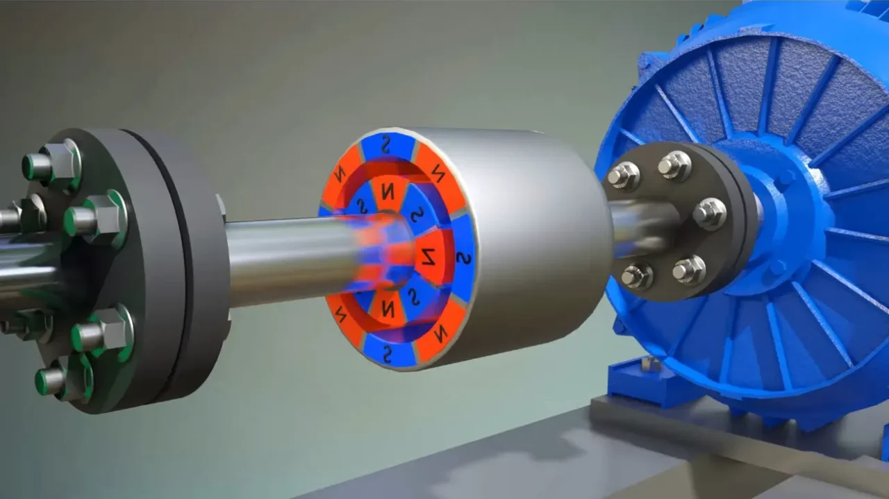
Fluid connectors: Transfer power through hydraulic oil rotation.
Rigid sleeves: Lock shafts together without flexing capacity.
Flexible elements absorb misalignment, whereas rigid sleeves provide exact shaft concentricity. Designers must analyze shaft thermal expansion before choosing a specific connector type. Lubricated metallic models deliver exceptional strength but demand ongoing maintenance routines. Non-lubricated elastomeric designs simplify maintenance by eliminating grease requirements entirely. Plant managers prioritize long-term reliability over initial procurement costs during selection. Standardizing on key types reduces inventory expenses in large warehouse facilities.
Analyzing the Performance of Flexible and Rigid Designs
Elastomeric jaw connectors utilize a rubber insert to prevent direct metal contact. This polyurethane spider dampens system vibrations and protects delicate sensor equipment. Disc styles use stainless steel packs to transmit torque without backlashes. These assemblies suit high-speed applications where precise positioning remains critical for production. Rigid sleeves excel in vertical pump shafts where zero deflection is necessary. A fluid industrial coupling relies on kinetic energy to accelerate turbine wheels. Hydraulic energy transfer provides smooth startup acceleration and protects electric grids from surges. Heavy conveyors utilize these fluid units to lift bulk materials safely. Monitoring ambient temperature limits prevents the rubber spider from melting during heavy operation. Engineers evaluate torque profiles before choosing between elastomer and metal components. Proper matching extends the operating lifespan of both shafts and seals.
Mechanical Specifications of Common Alloys
Metal selection determines the torque limits and fatigue life of machinery connectors. Factory designers compare physical properties to select the appropriate grade of steel. Carbon steel AISI 1045 offers robust tensile strength for standard utility operations. High-speed turbines require alloy steels like AISI 4140 to handle intense rotational stress. Aluminum alloys reduce system inertia and allow faster motor acceleration in packaging equipment. Corrosive environments demand stainless steel grades to prevent rust from seizing shaft joints. Standard specifications direct procurement teams toward cost-effective metal solutions for daily operations. Heat treatment processes alter metal grain structures to improve overall toughness and wear resistance. Testing laboratories verify chemical composition before certifying metal bars for high-speed use. Proper metallurgical analysis prevents sudden shaft fractures under sudden reverse load cycles. Table 1 details key mechanical characteristics of metals used in shaft connections.
| Material Grade | Tensile Strength (MPa) | Yield Strength (MPa) | Corrosion Resistance |
|---|---|---|---|
| AISI 1045 Carbon Steel | 585 | 310 | Low |
| AISI 4140 Alloy Steel | 655 | 415 | Medium |
| Stainless Steel SUS316 | 515 | 205 | High |
| Aluminum Alloy 7075 | 572 | 503 | Medium-Low |
Material Suitability for High-Stress Applications
Carbon steel delivers the necessary yield strength for general heavy manufacturing setups. It remains an economical option for dry, indoor environments where moisture is minimal. Marine industries select stainless steel SUS316 due to its superb chemical stability. High chloride environments cause rapid pitting in standard steels within a few weeks. Alloy steels like AISI 4140 withstand high fatigue stress in severe torque spikes. An industrial coupling crafted from this alloy carries heavy loads without permanent deformation. Aluminum components offer high strength-to-weight ratios but degrade at elevated temperatures. Operators balance cost and durability when choosing these critical system components. Corrosion-resistant alloys prevent costly chemical contamination during food production processes. Thermal expansion parameters dictate material selections in high-temperature boiler applications. Metallurgical quality directly influences the continuous operating life of the entire system.
Advanced Maintenance for an Industrial Coupling
Proper laser alignment tools ensure exact shaft concentricity during system installation. Mechanical wear accelerates significantly when technicians ignore angular or parallel offsets. Operators use dial indicators to measure shaft deflection before tightening mounting bolts. Thermal growth must be accounted for when aligning cold machinery systems. Hot operations cause metals to expand, changing the relative heights of connected shafts. Vibration analysis sensors detect minor misalignments before physical damage occurs. Technicians record baseline frequency spectrums to track deterioration over several months. Standard tolerance limits direct maintenance schedules to prevent sudden catastrophic motor failure. Table 2 lists the maximum permissible alignment tolerances for various shaft speeds. Following these parameters preserves bearings, seals, and connected gearbox components. Regular lubrication intervals remain necessary for metal grid and gear styles.
| Shaft Speed (RPM) | Parallel Tolerance (mm) | Angular Tolerance (Degrees) | Lubrication Interval |
|---|---|---|---|
| Under 1000 | 0.15 | 0.50 | 6 Months |
| 1000 to 1800 | 0.10 | 0.30 | 3 Months |
| 1800 to 3600 | 0.05 | 0.15 | Monthly |
| Above 3600 | 0.02 | 0.05 | Continuous / Oil Mist |
Data Analysis of Rotational Speed Boundaries
High rotational speeds impose immense centripetal forces on all connection elements. Tight parallel tolerances of 0.02 millimeters protect fast machinery from excessive heat. Large angular offsets create axial stresses that quickly destroy motor bearing balls. Every industrial coupling requires precise balancing to run smoothly at 3600 RPM. Unbalanced components induce structural vibrations that damage concrete machine foundations. Specialized balancing weights counteract minor manufacturing weight variations in cast hubs. Technicians verify balance grades using ISO standards before high-speed installation. Elastomeric parts do not require lubrication but demand inspection for ozone cracks. Chemical exposure embrittles polyurethane spiders, leading to sudden teeth breakage. Scheduled replacements during plant turnarounds prevent costly unscheduled shutdown events. Maintaining precise alignment records assists engineers in diagnosing recurring bearing failures.
Standards Compliance for Machinery Components
Global manufacturing standards dictate the design and testing of critical power transmission parts. Organizations like ANSI, ISO, and AGMA establish uniform rules for key sizes. Adhering to these specifications guarantees that replacement components fit existing drive shafts perfectly. A shaft coupling torque coupling meets these international engineering regulations for safe operations. Explosive environments require specialized ATEX certifications to prevent friction sparks from causing fires. Certified non-sparking metals shield chemical processing facilities from potential disaster risks. Manufacturers test these assemblies under cyclic dynamic loads to confirm fatigue limits. Quality control teams issue material test reports to verify exact chemical trace elements. Distributors supply these documents to end users to satisfy local safety inspectors. Using non-compliant components voids mechanical warranties and increases plant liability during accidents. Smart factories maintain high quality standards to ensure long-term operator safety.
FAQ
How does angular misalignment affect mechanical wear?
Angular misalignment forces connection parts to flex continuously during each shaft rotation cycle. This constant cyclic bending generates internal material friction and increases heat accumulation. Elastomeric inserts degrade quickly under high temperatures, losing their protective elasticity. Metal grids and gear teeth experience uneven surface pressure, accelerating local wear. Mechanical stress travels up the shaft, causing premature failure in motor bearings. Seals leak oil or grease when shafts wobble, letting destructive contaminants enter. Vibrations increase, loosening mounting hardware and creating extra noise inside factories. Proper alignment protocols minimize these risks and prolong machine life significantly. Laser calibration tools offer the highest accuracy during initial equipment setup. Routine inspections detect alignment shifts before serious mechanical damage occurs. Correcting offsets promptly prevents expensive emergency repairs on production lines.
What are the primary indicators of elastomeric element failure?
Visible rubber dust underneath rotating assemblies indicates severe wear of elastomeric spiders. Abnormal rattling noises signal that mating metal hubs are striking each other directly. Physical inspections reveal cracks, tears, or missing chunks in polyurethane insert bodies. Excessive play or backlash during shaft rotation shows advanced decay of elastomer wings. High heat coming from housing shields often signals continuous heavy overload conditions. Ozone exposure and chemical spills cause rubber elements to harden and crumble. Hardened inserts fail to absorb sudden load spikes, risking steel hub destruction. Preventive maintenance plans dictate regular replacement before physical breakage takes place. Technicians keep spare spiders in stock to ensure quick repairs during turnarounds. Recording operating temperatures helps identify premature aging issues in critical machinery. Upgrading to high-temperature polyurethane grades extends run times in harsh conditions.
Which applications require torsionally rigid connections?
Precision servo motor systems require zero backlash to maintain accurate positioning coordinates. Automated assembly lines rely on rigid sleeves to synchronize multiple moving parts. Paper printing presses need absolute shaft synchronization to prevent color registration errors. High torsional stiffness ensures that output shafts respond instantly to motor input. Metal disc designs provide the necessary rigidity while accommodating small misalignments. Heavy vertical mixer shafts employ rigid connections to support long suspended loads. These installations require perfect initial alignment because the hardware cannot flex. CNC machining centers demand solid metal clamps to execute rapid cutting sequences. Misalignment in these systems causes extreme stress, requiring high-grade alloy steels. Designers evaluate positioning accuracy needs before selecting rigid mechanical options over flexible. Standardizing on rigid styles simplifies the system design in low-vibration environments.