Worm gear basics are widely used in mechanical transmission systems that require controlled motion. These mechanisms convert rotational input into perpendicular output with high torque efficiency. Engineers often choose them for compact layouts and stable operation under heavy loads. Their structure supports smooth engagement and reduced vibration compared with many traditional systems. In industrial environments, worm gear setups help regulate speed and improve positional accuracy. Design considerations include friction control, material pairing, and lubrication strategy. Proper configuration ensures long-term stability in demanding applications. These systems are especially useful where space is limited but torque demand is high.
Fundamental Structure of Worm Gear Basics
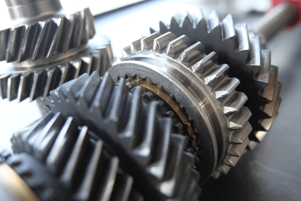
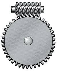
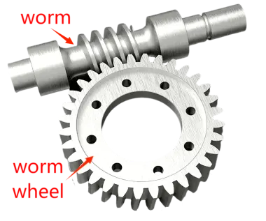
A worm gear system consists of a threaded worm and a matching wheel arranged at right angles. The worm acts like a screw driving the wheel teeth gradually. This contact pattern enables high reduction ratios in a single stage. Engineers optimize geometry to reduce backlash and improve meshing stability. Alignment precision is critical to avoid uneven wear and energy loss. Compared with spur gear helical gear configurations, worm systems achieve higher reduction in fewer steps. This structural advantage makes them suitable for compact machinery. Lubrication channels are often integrated to manage heat and reduce friction during continuous operation.
Worm Gear Basics Interaction and Motion Control
Motion transfer in worm gear systems relies on sliding contact between surfaces. This creates gradual engagement and smooth torque transmission. Heat generation is an unavoidable result of friction, requiring careful management. Lubricant selection directly influences efficiency and wear resistance. Engineers often optimize lead angle to balance self-locking and efficiency. In safety-critical systems, worm gear setups prevent reverse motion effectively. This characteristic improves operational security in lifting mechanisms.
Proper meshing reduces vibration and enhances stability under load. Misalignment can significantly shorten service life and increase noise levels.
Mechanical Advantage in Worm Gear Basics Systems
These systems deliver strong torque multiplication in compact configurations. Small input force can generate high output torque depending on ratio design. This makes them ideal for lifting and positioning machinery. Efficiency varies depending on friction, lubrication, and load conditions. Designers must carefully balance performance and energy loss. In many applications, torque consistency is more important than speed. Proper selection of ratio ensures controlled output movement. Engineers frequently simulate load conditions before finalizing designs. This ensures mechanical reliability in real-world operation environments.
Material Engineering in Worm Gear Systems
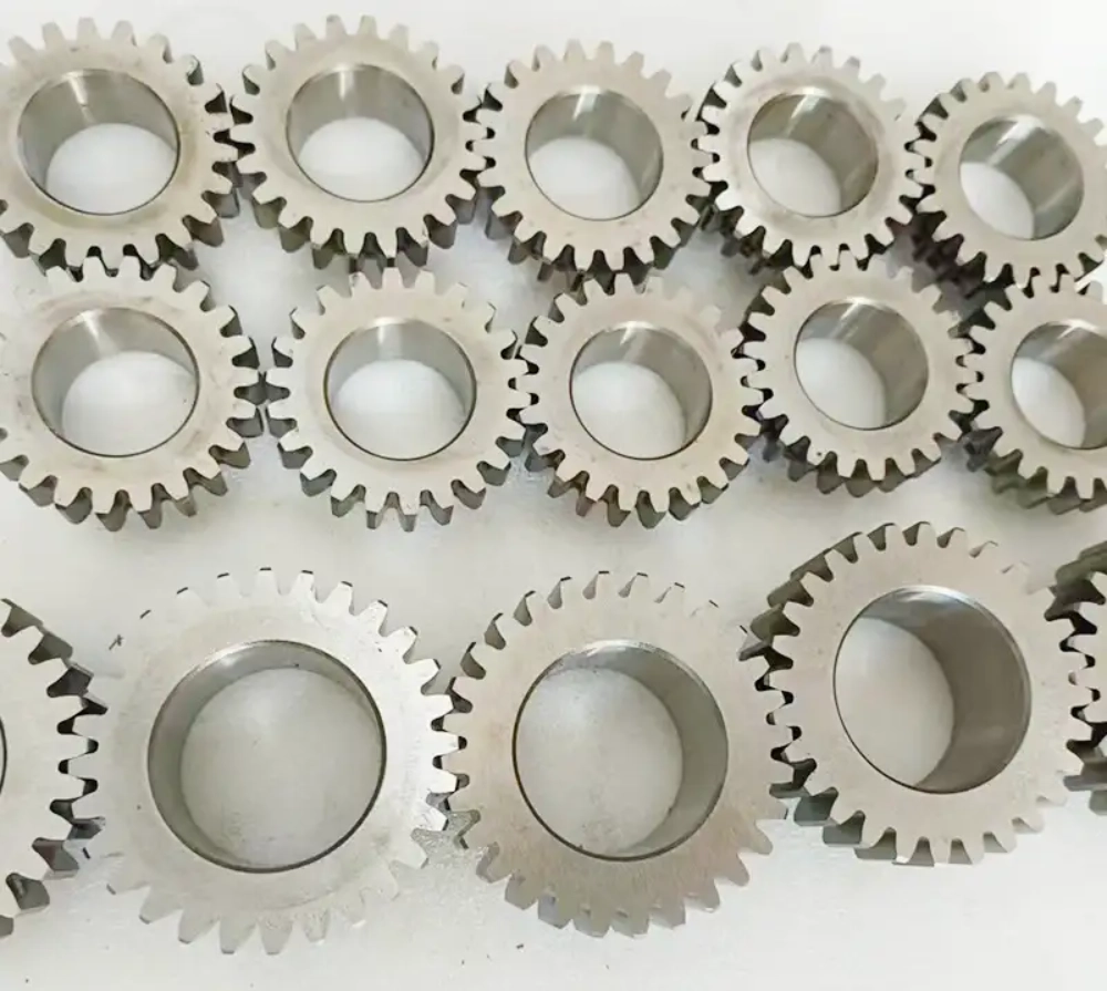
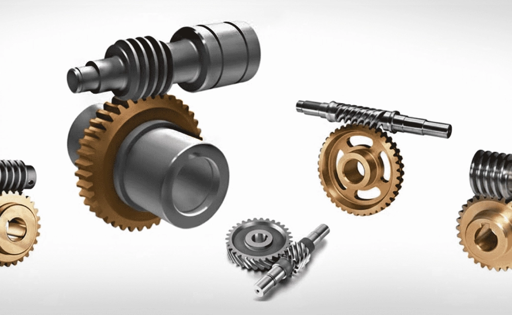
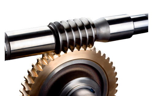
Material selection plays a crucial role in durability and performance. Worm shafts are commonly made of hardened steel for strength. Worm wheels often use bronze alloys to reduce friction and wear. This pairing prevents surface seizure under continuous load. Heat treatment improves hardness and extends service life. Surface finishing techniques enhance smooth interaction between components. Material compatibility also affects lubrication performance. In harsh environments, corrosion-resistant alloys are used for stability. Proper material pairing directly impacts maintenance frequency and system reliability.
Efficiency and Thermal Behavior in Worm Gear Basics
Friction remains the primary factor affecting efficiency in these systems. Sliding contact generates heat that must be dissipated effectively. Lubrication reduces wear and stabilizes temperature during operation. Efficiency is typically lower than other gear systems due to energy loss. However, design advantages often outweigh this limitation. Engineers adjust geometry to optimize contact pressure distribution. Cooling structures may be added to improve thermal stability. Lubricant viscosity must match operating conditions. Without proper thermal control, wear accelerates significantly.
Industrial Applications of Worm Gear Systems
| Application | Load Capacity | Operating Speed |
|---|---|---|
| Elevators | High | Low |
| Conveyors | Medium | Medium |
| Rotary tables | Medium-High | Low |
Industrial systems rely on worm gear basics for controlled motion and torque stability. Elevators require self-locking capability for safety. Conveyors depend on steady torque delivery under variable loads. Rotary tables benefit from precise positioning accuracy. These applications demonstrate how worm systems support multiple industries. Engineers select configurations based on load and duty cycle. Material and lubrication choices directly affect long-term reliability. System design must account for continuous operation stress and heat buildup.
Design Limitations and Mechanical Risks
Every worm system has inherent mechanical limitations. Heat generation restricts continuous high-speed operation. Wear increases if lubrication is insufficient or inconsistent. Misalignment leads to uneven contact stress and vibration. Backlash can reduce precision in positioning systems. Engineers must carefully design housing rigidity to avoid deformation. Proper assembly is essential for long-term stability. Load overload may permanently damage contact surfaces. Despite limitations, these systems remain valuable in compact designs.
Failure Analysis in Worm Gear Systems
| Failure Type | Main Cause | Prevention Method |
|---|---|---|
| Overheating | Excess friction | Improved lubrication |
| Tooth wear | Misalignment | Precision assembly |
| Backlash increase | Improper adjustment | Correct meshing setup |
Failure analysis shows that thermal and mechanical stress are the primary risks. Overheating reduces efficiency and accelerates degradation. Wear typically results from incorrect alignment or poor lubrication.
Backlash issues affect precision and stability. Engineers mitigate risks through proper design and maintenance planning. Monitoring systems help detect early signs of degradation. Correct setup significantly improves service life. These practices ensure consistent performance in industrial environments.
Maintenance Strategy for Worm Gear Systems
Maintenance is essential for long-term reliability in mechanical systems. Regular lubrication ensures smooth operation and reduces friction. Inspection schedules help identify early wear patterns. Alignment checks prevent uneven load distribution. Engineers often monitor temperature during operation. Oil analysis can reveal contamination or degradation. Preventive maintenance reduces unexpected downtime. Proper storage conditions also extend component lifespan. In worm gear basics, consistent care ensures stable performance over time.
Comparison with Alternative Gear Systems
Different gear types serve different mechanical needs. A Precision bevel gear worm gear configuration provides angled power transmission advantages. However, worm systems excel in compact torque conversion. Spur and helical gears are more efficient at high speed. Worm systems prioritize torque and control rather than speed. Selection depends on design constraints and application goals. Engineers evaluate efficiency, space, and load requirements. Each system offers unique advantages depending on use case.
FAQ
What are worm gear systems used for?
Worm gear systems are used to transmit motion between perpendicular shafts. They provide high torque and controlled speed reduction. Applications include elevators, conveyors, and industrial actuators. Their compact structure makes them suitable for space-limited designs. Self-locking ability improves safety in lifting systems. Engineers choose them when precision and stability are more important than efficiency. Proper lubrication and alignment are essential for long-term performance. These systems remain widely used in industrial engineering environments.
How efficient are worm gear systems?
Efficiency depends on friction, lubrication, and load conditions. Typical efficiency ranges from moderate to relatively low compared to other gears. Sliding contact causes energy loss and heat generation. Multi-start designs improve efficiency but reduce self-locking ability. Engineers optimize geometry to balance performance and safety. Lubrication plays a critical role in reducing friction. Thermal management also affects overall efficiency. Despite limitations, they are chosen for torque and control advantages.
What materials are best for worm gear systems?
Steel and bronze combinations are most commonly used. Steel provides strength for the worm shaft. Bronze reduces friction on the wheel surface. This pairing minimizes wear under continuous load. Heat treatment enhances durability and resistance to fatigue. Material compatibility affects lubrication efficiency. Corrosion resistance may be required in harsh environments. Engineers select materials based on load, speed, and operating conditions. Proper selection extends system lifespan significantly.