High-torque industrial machinery relies on precise mechanical connections to prevent disastrous rotational failures. Engineers must match shafts and hubs with absolute precision to maintain driveline integrity. Selecting an incorrect coupling bore keyway specification often triggers shaft slippage. This misalignment rapidly damages expensive drive components. Power transmission systems require strict adherence to dimensional standards. Machinists use standardized charts to cut keyseats. These profiles accommodate the exact dimensions of mechanical keys. Proper physical tolerances prevent rotational play under varying operational loads. Heavy machinery requires durable connections for continuous operation. Experienced operators prioritize correct fit over quick installation steps. This diligence ensures reliable long-term torque transmission.
Critical Parameters for a Coupling Bore Keyway Specification
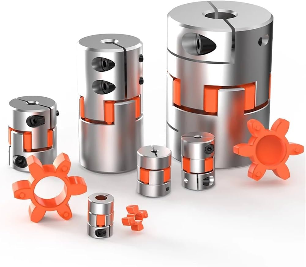
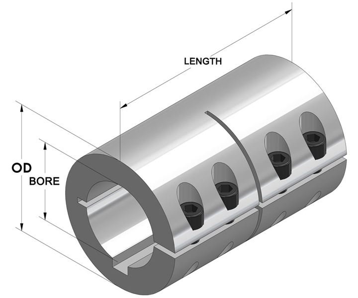
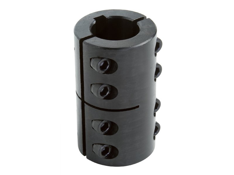
Mechanical power transmission relies heavily on standard interface geometries. Engineers utilize a shaft coupling torque coupling setup to handle extreme rotational forces. Standardized keyways prevent relative rotation between mating cylindrical parts. This mechanical locking method secures pulleys, gears, and rigid couplers. Operators measure nominal shaft diameters before choosing hardware sizes. Precise caliper measurements eliminate guesswork during the installation process. Each specific shaft diameter corresponds to a standard key size. Industrial standards define these relationships to ensure system compatibility. Heavy-duty applications require robust keys to resist shear stress. Failure to match these parts leads to key roll. Solid steel keys must fit snugly within their respective hub channels. Proper selection guarantees smooth power transfer.
Imperial Standards for Industrial Shaft Keyways
| Shaft Diameter (Inches) | Nominal Keyway Width (Inches) | Nominal Keyway Depth (Inches) |
|---|---|---|
| 5/16 to 7/16 | 3/32 | 3/64 |
| 1/2 to 9/16 | 1/8 | 1/16 |
| 5/8 to 7/8 | 3/16 | 3/32 |
| 15/16 to 1-1/4 | 1/4 | 1/8 |
| 1-5/16 to 1-3/8 | 5/16 | 5/32 |
Analyzing Imperial Dimensions for Smooth Power Transmission
Metric Standards for Modern Rotating Equipment
| Shaft Diameter (mm) | Nominal Keyway Width (mm) | Nominal Keyway Depth (mm) |
|---|---|---|
| 6 to 8 | 2 | 1.0 |
| 9 to 10 | 3 | 1.4 |
| 11 to 12 | 4 | 1.8 |
| 13 to 17 | 5 | 2.3 |
| 18 to 22 | 6 | 2.8 |
How Metric Standards Affect Coupling Bore Keyway Specification Practices
Global manufacturing hubs depend on metric dimensions to maintain operational consistency. Standardizing on millimeter measurements simplifies international parts sourcing. Machinery designers consult a precise coupling bore keyway specification to ensure proper clearances. This standardization coordinates mating parts from different overseas suppliers. Technicians use precision grinding tools to finish metric slots perfectly. Metric parallel keys must fit with precise lateral contact. Even a tiny mismatch of one millimeter ruins the connection completely. High-vibration environments demand tighter interference fits for security. Maintenance crews replace worn keys during routine system inspections. Applying anti-seize compound facilitates easier disassembly later. Engineers specify tolerance classes like Js9 to prevent hub sliding. These tight dimensional guidelines protect rotating gear boxes.
Determining the Proper Tolerance Classes for Secure Fits
Selecting correct tolerance classes prevents slippage under fluctuating mechanical loads. Machine designers identify the difference between clearance and interference fits. Clearance fits allow easy assembly and disassembly of components. These configurations work well in standard conveyor systems. Conversely, interference fits require high hydraulic press force. High-stress environments utilize tight fits to prevent mechanical fretting. Technicians evaluate the specific operational demands of their systems.
Machining Techniques for Precision Keyway Production
Machinists employ specialized milling cutters to produce high-precision keyseats. End mills cut parallel channels into solid steel shafts. Shaper machines create the corresponding internal slots in hubs. Broaching operations provide extremely accurate internal dimensions rapidly. Proper cutting speeds prevent excess heat generation during machining. Heat distortion compromises the metallurgy of critical drive shafts. Engineers check finished slots using precise go-no-go gauges. This quality check ensures compliance with international engineering drawings. Any deviation in width leads to rapid key failure. Operators reject components that do not meet nominal standards. Investing time in precision machining pays off in longevity. Well-cut seats maintain uniform load sharing across the drive.
Engineering Procedures for Proper Sizing Verification
- Measure the exact outside diameter of the driving steel shaft.
- Determine the nominal torque requirements of the driven application.
- Identify standard keyway widths and depths using industrial tables.
- Verify the specific tolerance class for the hub connection.
- Select an appropriate mechanical key material for shear resistance.
Implementing Sizing Verification Processes in Industrial Shops
Following a structured technical checklist prevents major drive system misalignments. Operators verify each critical parameter to avoid costly mechanical downtime. Referencing a standard coupling bore keyway specification guarantees part compatibility instantly. This practice prevents engineers from ordering mismatched replacement hubs. Measuring tools must have current calibration certificates for accuracy. Small dimensional mistakes lead to catastrophic failures under load. Maintenance technicians document every step of the verification process. This recording helps analyze future wear patterns on keys. Team leaders approve final dimensions before releasing parts for production. Standardizing this procedure minimizes human error in repair shops. Consistent engineering habits improve overall factory efficiency and safety.
Material Selection and Keyseat Sizing Integrity
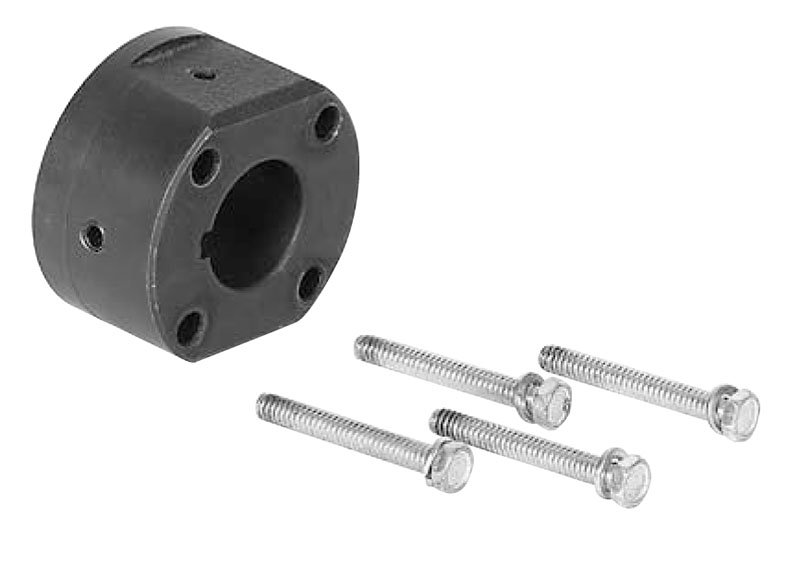
High-quality keyways require proper material combinations to resist wear. Carbon steel keys offer high tensile strength for normal applications. Stainless steel keys resist corrosion in harsh chemical processing plants. Heavy vibration environments utilize a flexible coupling elastomeric coupling setup to damp shock. This configuration absorbs sudden torque spikes before they reach keyways. Elastomeric inserts cushion the mechanical interface during motor startup. Engineers select tough key materials to prevent sudden shear failures. Softer metals deform easily and ruin the precise shaft fit. Hardened keys protect expensive components from receiving extreme point loads. Maintenance specialists inspect components for micro-cracks using dye penetrants. Replacing damaged keys promptly saves the main drive shaft.
Root Causes of Keyway Failures in Mechanical Drives
Torsional fatigue remains the primary cause of industrial keyway failures. Repetitive start-stop cycles subject the metal keys to alternating stresses. These stresses cause micro-fractures to propagate from sharp slot corners. Designers specify radiused keyways to distribute these concentrated forces safely. Filleted corners eliminate localized stresses that lead to rapid cracking. Severe overloading triggers plastic deformation across the key face. This deformation results in a loose connection and audible clacking. Plant operators must address noise immediately to prevent shaft destruction. Loose components accelerate fretting corrosion inside the assembly hub. Regular lubrication with specialized paste minimizes metal-to-metal wear. Experienced teams replace keys whenever they uncouple connected machinery.
Best Practices for Keyway Inspection and Maintenance
Systematic inspections protect industrial drivetrains from catastrophic torque failures. Maintenance technicians inspect shafts regularly during scheduled factory shutdowns. Checking the coupling bore keyway specification ensures correct dimensions remain intact over time. Wear patterns reveal hidden misalignments before they cause major trouble. Engineers use precise dial indicators to check shaft runout values. Excessive runout damages both the key and neighboring bearings. Operators clean the slots thoroughly using wire brushes and solvents. Removing rust and debris allows for exact precision measurements. Applying the correct torque to hub setscrews prevents axial movement. This locking force keeps the mechanical key from sliding outward. Preventive care extends the operational lifespan of heavy industrial equipment.
Final Engineering Recommendations for Optimal System Design
Successful system integration requires meticulous planning and attention to detail. Engineers must consult current ANSI B17.1 and DIN 6885-1 standards during design. These frameworks establish precise tolerances for square, rectangular, and parallel key designs. Additionally, the ANSI/AGMA 9002-B04 standard defines clearance and interference fits for flexible couplings. Correctly matching bores and keyways ensures optimal power transmission and safety. Double keys offer excellent load distribution for extremely demanding applications. Designers utilize splines when torque requirements exceed standard keyway limits. Proper documentation keeps maintenance crews informed of exact hardware sizes. Sourcing premium keys from certified manufacturers prevents unexpected metal fatigue. Technical teams must prioritize long-term durability over initial component cost. Quality mechanical connections protect valuable factory assets from structural failure. Following standard engineering processes minimizes operational risks across the facility. Ultimate system reliability stems from exact dimensional matches and careful installations.
FAQ
What are the mechanical consequences of mismatched coupling keyway dimensions?
Can metric keys function safely in imperial shafts?
Mixing metric and imperial components creates high structural risks. Millimeter keys do not fit inch-based slots properly. A tiny clearance allows the key to tilt under load. This tilting concentrates stress on thin slot edges. Heavy loading soon shears the mismatched drive key. Operators must use the correct units for all parts. Matching imperial shafts with metric hubs requires step keys. These special components bridge the difference between unit standards. Engineers specify custom parts to prevent expensive mechanical failure. Precise conversions guarantee safe plant operations over time.
How does a deep keyseat impact overall shaft strength?
Cutting a slot into a shaft reduces its cross-sectional area. This reduction lowers the overall torsional strength of the component. Deep keyseats create significant stress concentration zones. Under heavy loads, cracks begin at these sharp corners. Engineers use radiused slot ends to minimize stress concentration. Standard tables specify safe cutting depths to protect components. Machinery operators must avoid custom deep cuts without engineering approval. Excess material removal leads to sudden shaft fracture under load. Proper machining depth balances torque transfer capacity with structural integrity. Regular inspections help identify early fatigue cracks before failure occurs.