Valve Handwheel Replacement: Parts and Fit Checklist
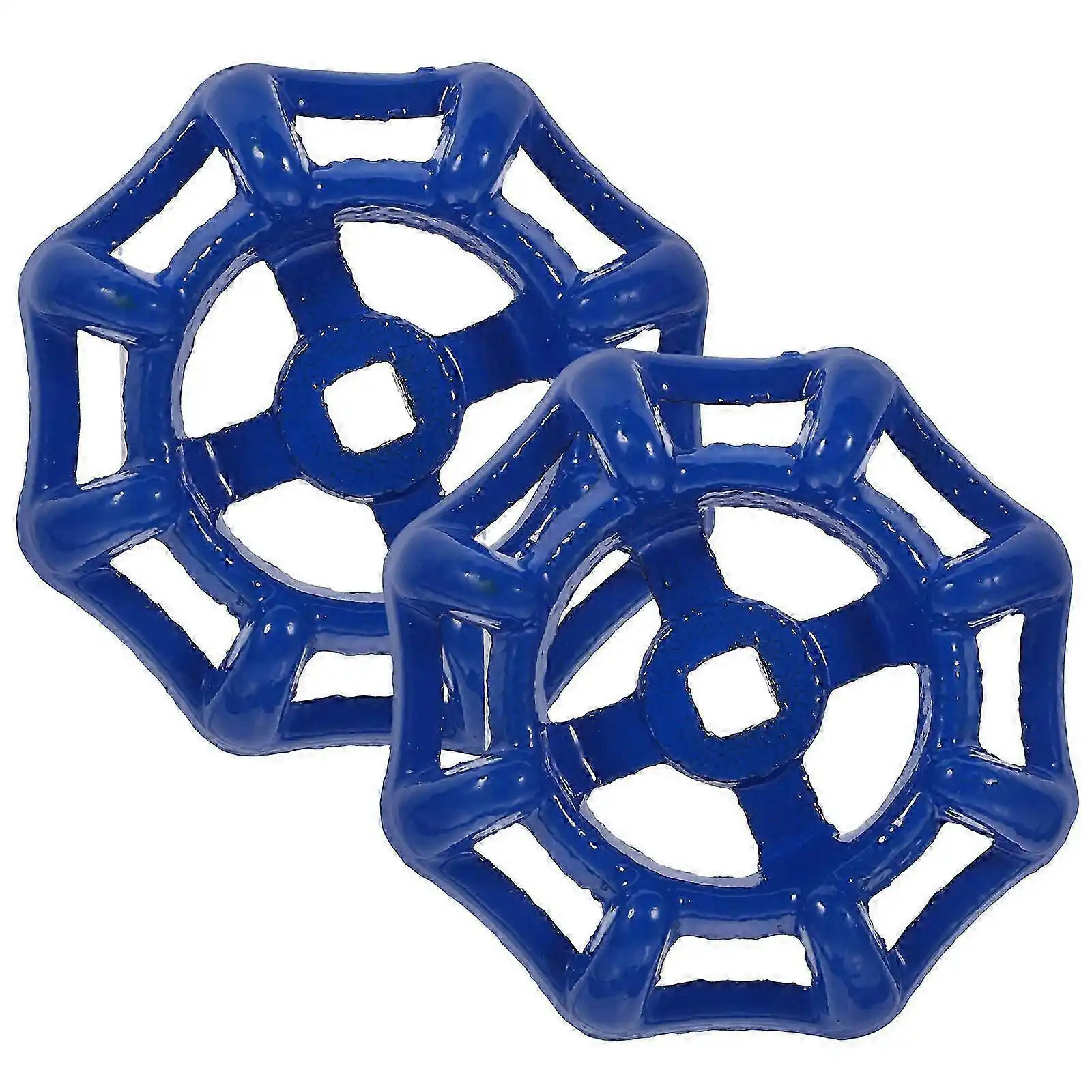
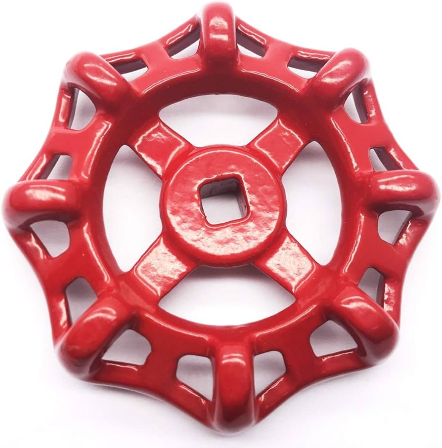
A valve handwheel replacement is often prompted by a broken rim, a loose hub or a wheel that no longer lets the operator turn the stem comfortably. Ordering by outside diameter alone is risky: two wheels of the same size may have different bores, keys, flats, splines or retaining hardware. The safest starting point is the valve manufacturer’s part information and a clear record of the existing stem connection.
This guide helps maintenance teams and buyers define a replacement part before ordering. When evaluating industrial machine handwheels, buyers should also verify compatibility with the valve’s operating mechanism. It does not replace the valve manufacturer’s service procedure or the site’s energy-control rules.
First, identify the valve and the failure
Record the valve maker, model, size and serial or tag number if available. Photograph the complete assembly, the hub and the retaining arrangement before anything is removed. Note whether the wheel is cracked, distorted, missing a grip or simply loose. A loose wheel may be a damaged key or fastener rather than a failed wheel. A wheel that is hard to turn may indicate a valve or gearbox problem; fitting a larger wheel could conceal the problem and overload the equipment.
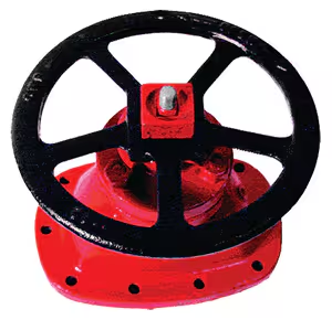
Check whether the wheel is connected directly to the stem or to a gearbox input shaft. These are different interfaces. Confirm the required direction of operation, any open/close indication and whether the handwheel has a fixed or revolving handle.
Control the maintenance risk
Before inspection or replacement, have authorized personnel assess all energy sources and stored pressure. Follow the site’s lockout/tagout and depressurization procedure where applicable. A handwheel is an operating component; removing it on a live or inadequately isolated system can create an unexpected movement or release hazard. Do not treat this article as permission to work on a pressurized valve.
The actual sequence, tools, fastener torque and return-to-service test must come from the valve maker and the site procedure. If those instructions are unavailable, identify the valve and obtain them before work proceeds.
Measure the connection, not just the wheel
The replacement specification should include:
- Outside diameter and rim or spoke style, including grip clearance.
- Hub outside diameter, hub height and available space around guards or pipework.
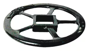
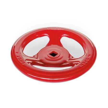
- Bore shape and size: round, square, flat, keyed, splined or another profile.
- Shaft dimensions and engagement length, measured from the actual mating feature.
- Retention method, such as a nut, screw, pin or key, including thread and washer details.
- Material and coating appropriate to the service environment, confirmed against the original equipment requirements.
Measurements from a worn or broken wheel can be misleading. Compare the wheel, the shaft and the manufacturer’s drawing. Photograph the connection with a ruler in view, but use calibrated measurements for ordering. A sample wheel or dimensioned sketch is often the most reliable way to resolve an uncommon bore.
Check operating clearance and human factors
A replacement should let an operator reach the rim without trapping fingers against nearby equipment. Confirm that the full rotation path clears guards, panels, insulation and adjacent handwheels. A revolving handle can improve grip in some applications, but it also changes the clearance envelope. Match the original operating arrangement unless the valve maker approves a change. Aluminum solid handwheels may suit applications requiring a lightweight operating wheel, provided their dimensions and connection features match the valve specifications.
Diameter affects the leverage available to the operator. Do not increase it simply to make a stiff valve easier to turn: the valve stem, gearbox and stops may have limits. Address abnormal operating resistance at its source.
Confirm fit and function after installation
The authorized technician should inspect the bore and shaft for damage, fit the specified retaining parts and follow the maker’s fastening instructions. The connection should seat correctly rather than wobble or bottom out prematurely. After the system is made safe for testing under the site’s procedure, confirm the wheel turns in the expected direction, the valve reaches its intended positions and no interference occurs through the operating range.
Record the installed part number and any changed hardware. If the wheel slips, binds or needs unusual force, stop and investigate instead of tightening it by guesswork.
What to send with a replacement enquiry
Provide the valve model or nameplate, photos of the installed and removed wheel, shaft and bore measurements, desired wheel diameter, environment and quantity. Include the original drawing or sample when possible. State whether the request is for an exact OEM replacement or for a reviewed alternative. That distinction prevents a visually similar wheel from being mistaken for an approved substitute.
Diagnose the connection before ordering
The first inspection should separate damage to the wheel from damage to the parts that hold it. A crack through a spoke or hub points to the wheel. A sound wheel that turns without moving the stem may indicate a missing key, stripped bore, loosened fastener or damaged gearbox input. A wheel that rocks on the shaft can wear both parts further if it remains in service. Record what moves relative to what; that observation helps the equipment owner decide whether the order is for a wheel, retention hardware or a larger valve repair.
Do not use a new wheel to force a valve that has become unusually stiff. Compare the current operating force with the valve maker’s guidance and maintenance history. The underlying issue might involve packing, internal deposits, a damaged gearbox or another fault that the wheel alone cannot solve. A technician should resolve that fault before selecting a replacement with different leverage.
Compare exact replacement with a reviewed alternative
An original part number is the clearest route when it remains available. Where the part is obsolete, an alternative can be evaluated against the original interface and operating envelope. The review should cover bore geometry, hub height, retention, wheel diameter, grip location, material and direction markings. Small differences may matter: a taller hub can prevent a retaining nut from engaging fully, while a thicker rim can collide with a nearby guard.
A dimensioned replacement drawing is more useful than a statement that a wheel “fits the same valve size.” Valve nominal size describes the flow equipment, not necessarily the handwheel connection. If a supplier proposes a design change, ask the equipment owner or valve maker to approve it before purchase. Keep the approval with the maintenance record so a later replacement does not revert to an incompatible part.
Plan the installation and handover record
The maintenance plan should identify who will isolate and verify the system, who will perform the mechanical work and who can authorize return to service. Record any special tools, keys, fasteners or seals required by the maker’s instructions. Avoid reusing damaged retention hardware merely because it can still be tightened. The technician should confirm that the new wheel is seated, retained and able to travel through the permitted range under the approved procedure.
The handover record can include the old and new part identifiers, photographs of the connection, the reason for replacement and the outcome of the functional check. This gives the next maintenance team a reliable starting point. It also helps distinguish a recurring handwheel failure from a recurring valve or gearbox problem.
Frequently Asked Questions
Can any wheel with the same outside diameter be used?
No. The bore, engagement, retention, clearance and permissible operating arrangement must also match.
Does a larger wheel solve a hard-to-turn valve?
Not necessarily. Excessive resistance may be a valve or gearbox fault, and extra leverage can damage components.
Is replacement safe while the line is operating?
That decision belongs to the site’s authorized personnel and the valve manufacturer’s procedure. Assess isolation, pressure and stored energy before maintenance.