The process to measure bushing size correctly is a core requirement in mechanical engineering inspection work. Engineers depend on dimensional accuracy to ensure stable rotation and reduced friction in assemblies. Even small deviations can cause vibration, heat buildup, and premature wear in machinery systems. In industrial environments, technicians apply standardized methods to ensure repeatable results across production batches. Accurate preparation before inspection reduces uncertainty and improves measurement consistency. Calibration of instruments is essential before any physical checking begins. Environmental stability also plays a key role in ensuring reliable readings. Proper training ensures operators understand correct positioning techniques during measurement tasks. This foundation supports long term mechanical reliability in demanding applications.
Key Standards Used in Engineering Systems
International engineering standards define how components are evaluated in industrial production systems. ISO and ANSI frameworks provide unified rules for dimensional tolerance and fit classification. These systems ensure compatibility between parts manufactured in different regions. Engineers use tolerance charts to determine acceptable deviation ranges during inspection. Standardized documentation improves communication between design and manufacturing teams. Quality assurance departments rely on these references during final product validation. Consistency in interpretation reduces assembly failure risks in complex machinery. These standards also support automation in modern production lines. Reliable classification systems improve efficiency in global supply chains.
Essential Tools Used in Measurement Processes
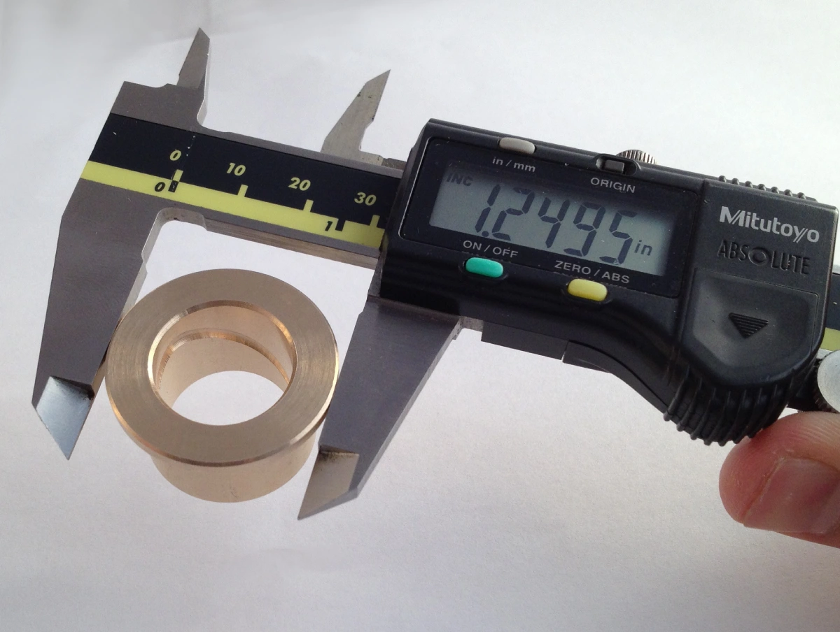
Precision instruments are required to measure bushing size correctly in workshop and factory environments. Digital calipers allow quick verification of internal and external dimensions. Micrometers provide higher accuracy for tight tolerance engineering requirements. Bore gauges are used to assess internal diameter variations with high repeatability. Calibration blocks ensure all instruments maintain certified accuracy levels over time. Temperature controlled environments help reduce thermal expansion errors during inspection. Tool selection depends on required precision level and component application. Regular recalibration prevents drift in long term usage. Proper handling techniques reduce operator induced measurement deviations significantly.
Step-by-Step Engineering Measurement Workflow
Engineers follow structured procedures to measure bushing size correctly in controlled environments. The first step involves cleaning the component surface to remove debris and oil. Contamination can distort readings and reduce measurement reliability. Internal diameter is measured using a bore gauge with careful alignment. External diameter is then checked using a calibrated micrometer. Length measurement completes the full dimensional profile assessment.
Multiple readings are taken to minimize random error influence. Each value is recorded under stable environmental conditions. Final results are compared with engineering tolerance specifications. Documentation ensures traceability for quality control audits and production verification.
Common Errors in Industrial Measurement
Incorrect alignment of instruments often leads to inaccurate dimensional results in industrial inspection. Calibration drift in tools introduces systematic deviation during repeated measurement cycles. Temperature changes can expand or contract metal components during testing. Worn instruments reduce repeatability and reliability of recorded values. Excessive force during measurement may deform softer materials slightly. Human positioning errors create angular inconsistencies in readings. Surface wear on components can also mislead interpretation of actual size. Vibrations in factory environments affect instrument stability during measurement. Proper training and maintenance reduce these common operational mistakes effectively.
Material Influence on Dimensional Accuracy
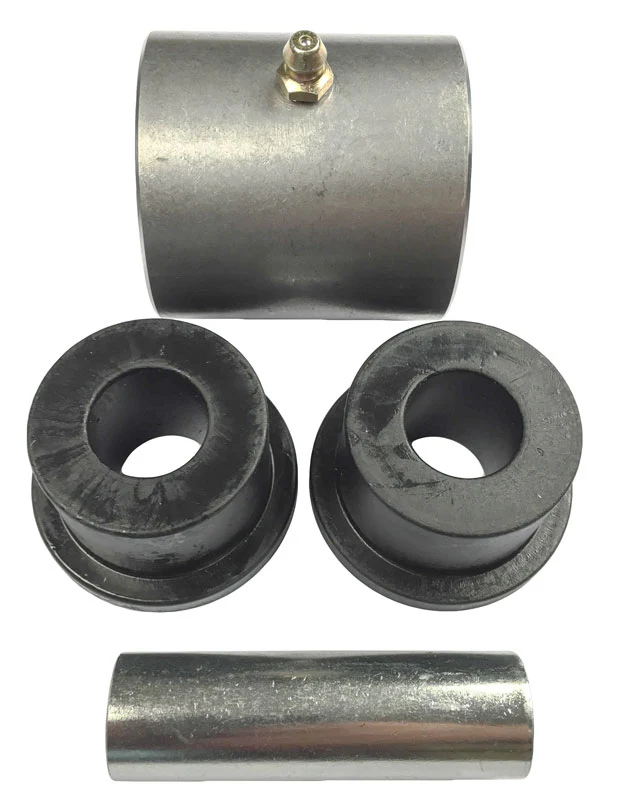
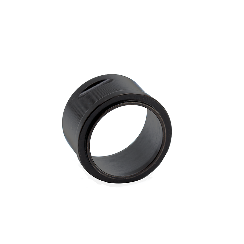
Material selection directly affects how engineers measure bushing size correctly in practical applications. Different alloys respond differently to temperature and pressure conditions. A Brass bushing with oil groove is often used to improve lubrication retention and reduce friction in rotating systems. Bronze materials provide excellent wear resistance under heavy load conditions. Polymer variants offer flexibility but are more sensitive to temperature variation. Elastic deformation may temporarily alter measured values under stress. Material hardness influences contact behavior between tool and surface. Engineers must consider thermal expansion coefficients during evaluation. Understanding material behavior ensures accurate interpretation of measurement results.
Result Interpretation in Engineering Practice
Interpreting dimensional results requires understanding tolerance categories used in mechanical design. Engineers compare measured values against predefined specification limits. Loose fits allow easier assembly but reduce positional stability. Interference fits improve mechanical strength under dynamic load conditions. Transition fits balance ease of assembly with precision alignment.Deviations beyond tolerance indicate wear or manufacturing inconsistencies. Statistical analysis helps identify production variation trends across batches. Proper interpretation ensures compatibility between mating components. Accurate evaluation supports long term equipment performance and reliability.
Maintenance Factors Affecting Long Term Stability
Operational conditions significantly influence how engineers measure bushing size correctly over time. Lubrication quality directly affects wear rate between moving surfaces. Contaminants increase abrasion and accelerate dimensional degradation. Repeated load cycles gradually alter internal geometry under stress. Temperature fluctuations cause expansion and contraction in materials. Scheduled inspections help detect early stage dimensional changes. Preventive maintenance reduces unexpected system failures effectively. Proper storage conditions preserve original manufacturing tolerances. Maintenance discipline ensures consistent mechanical performance in industrial systems.
Industrial Applications and Usage Scenarios
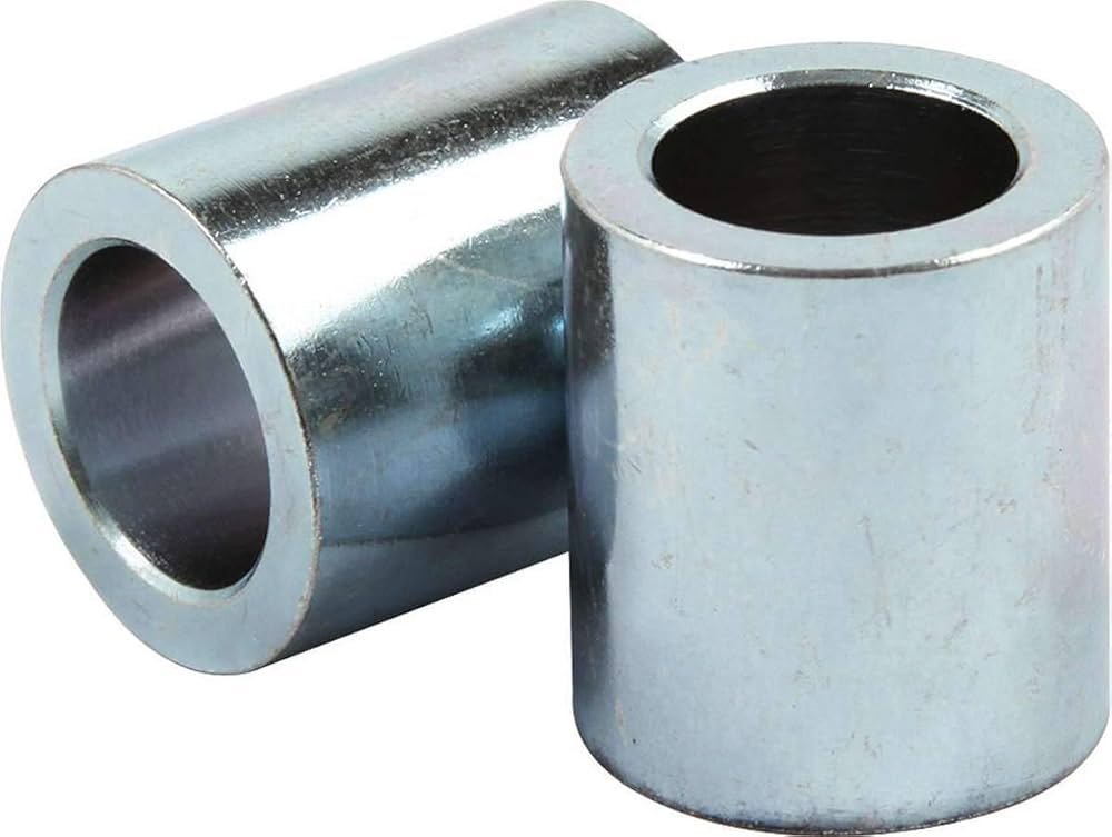
Many industries rely on precise dimensional control for safe mechanical operation. Automotive systems use bushings in suspension and steering assemblies. Hydraulic systems depend on tight tolerances for pressure stability. Aerospace engineering requires extremely strict dimensional accuracy for safety critical components. Heavy machinery applications demand durability under high load conditions. Industrial stainless steel bushing is commonly used in corrosive or high moisture environments. Robotics systems require consistent rotational precision for accuracy. Energy turbines depend on stable shaft alignment for efficient operation. Precise sizing improves performance across all mechanical industries.
Standard Bushing Size Reference Table
| Type | Inner Diameter | Outer Diameter | Application |
|---|---|---|---|
| Bronze | 10–50 mm | 15–60 mm | Heavy Load Systems |
| Polymer | 5–40 mm | 10–55 mm | Low Friction Systems |
| Steel | 8–60 mm | 12–70 mm | Industrial Machinery |
This reference table supports engineers during early design and procurement stages. It helps match component dimensions with system requirements. Standardized ranges reduce selection errors in industrial environments. Engineers use these values to ensure compatibility between parts. Accurate interpretation improves mechanical system reliability significantly.
Tool Calibration and Accuracy Table
| Tool | Calibration Cycle | Accuracy | Usage |
|---|---|---|---|
| Digital Caliper | 3 Months | ±0.02 mm | General Measurement |
| Micrometer | 6 Months | ±0.001 mm | Precision Work |
| Bore Gauge | 6 Months | ±0.005 mm | Internal Checks |
Calibration control ensures long term measurement reliability in industrial environments. Regular verification reduces drift in repeated usage. Consistent accuracy improves quality assurance outcomes. Engineers depend on stable instruments for production validation tasks. Proper calibration practices support manufacturing efficiency.
Measurement Workflow Using Structured Steps
- Clean all surfaces before inspection begins
- Select calibrated instruments based on tolerance level
- Measure internal diameter using bore gauge
- Check external diameter using micrometer
- Record all values under stable conditions
- Compare results with specification sheets
This structured workflow ensures repeatable accuracy in industrial environments. Each step reduces variability between operators. Proper sequencing improves measurement consistency significantly. Documentation supports traceability during audits. Engineers rely on this method for quality assurance processes.
Real Industrial Measurement Scenarios
Field conditions require engineers to measure bushing size correctly under less controlled environments. Temperature variation and vibration can influence measurement stability. Components must be isolated before inspection begins. Portable instruments are often used in maintenance operations. Data recording ensures traceability for future reference. Cross team verification improves measurement reliability. Environmental factors must be minimized when possible. Experience plays an important role in interpreting uncertain readings. Accurate field measurement supports long term equipment performance.
FAQ
What tools are best for measuring bushing size accurately?
Accurate measurement depends on selecting the correct instruments for each tolerance requirement. Digital calipers are commonly used for general dimensional checks. Micrometers provide higher precision for tight engineering tolerances. Bore gauges are essential for internal diameter measurement tasks. Engineers often combine multiple tools for cross verification purposes. Calibration ensures instruments maintain long term accuracy. Environmental stability reduces external influence on readings. Proper handling techniques prevent operator induced errors. Tool selection directly impacts measurement reliability and engineering quality outcomes.
How often should bushing size be checked in machinery?
Inspection frequency depends on operating load and environmental conditions. High stress systems require frequent dimensional monitoring schedules. Preventive maintenance programs define inspection intervals based on usage intensity. Critical machinery may require monthly or quarterly checks. Lower stress applications may follow annual inspection cycles. Wear rate analysis helps determine optimal timing. Lubrication quality also influences inspection frequency decisions. Regular monitoring prevents unexpected mechanical failures. Consistent evaluation improves system reliability and safety performance.
What causes bushing size variation over time?
Dimensional variation occurs due to multiple operational and environmental factors. Friction wear gradually removes surface material during operation. Thermal expansion and contraction affect structural stability. Improper lubrication accelerates degradation of contact surfaces. Excessive mechanical load can cause deformation under stress. Contaminants increase abrasive wear rates over time. Material fatigue develops after repeated stress cycles. Environmental humidity may also contribute to variation. Regular inspection helps detect early changes effectively.