Press fit vs slip fit defines two essential assembly methods in mechanical engineering. Manufacturers rely on these fits to control motion and stability. Each method follows strict tolerance and interference rules. Press fit creates a tight connection between mating parts. Slip fit provides controlled clearance for smooth movement. Engineers evaluate load, stress, and material properties carefully. Incorrect selection may cause failure or excessive wear. Many industries apply both methods in static or dynamic systems. Automotive, aerospace, and heavy machinery demand high precision. This comparison explains performance, cost, and manufacturing impact. Strong technical knowledge improves durability and production efficiency. B2B buyers often prioritize reliability and repeatability in large-scale production.
Definition And Fundamental Concepts
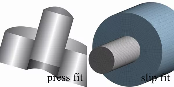
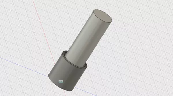
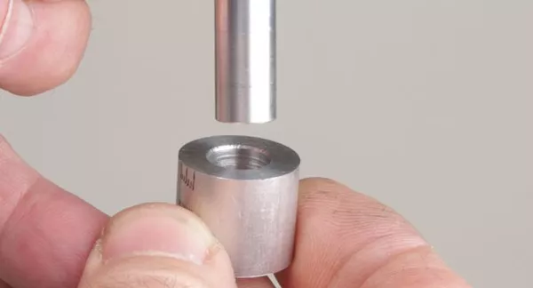
Press fit uses intentional interference between two components. The shaft diameter slightly exceeds the hole size. Assembly requires force to achieve a secure connection. Slip fit uses a designed clearance between mating parts. Components slide together without resistance during assembly. Engineers define tolerance ranges based on application needs. Press fits prevent relative movement after installation. Slip fits allow controlled motion or alignment flexibility. Both methods follow ISO and ANSI standards. Fit classification depends on clearance or interference values. Designers consider load direction and operating conditions. Each fit type supports different functional goals. Manufacturing teams must ensure precise dimensional accuracy. Proper fit selection directly influences system reliability and lifespan.
Mechanical Principles Behind Press Fit Assemblies
Press fit relies on elastic deformation of materials. Components compress slightly during assembly under applied force. Contact pressure generates friction between mating surfaces. This friction prevents movement under operational loads. Engineers calculate interference values based on material properties. Excess interference increases stress and risk of damage. Insufficient interference reduces holding strength significantly.
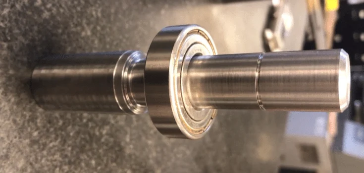
Surface roughness affects friction and contact area. Lubrication may assist assembly but reduce grip strength. Thermal methods sometimes support installation processes. Heating or cooling temporarily changes material dimensions. Press fit suits high-load and vibration-resistant applications. Bearings and gears commonly use this method. Strong bonding ensures structural integrity. However, removal often requires destructive techniques.
Functional Behavior Of Slip Fit Connections In Industrial Design
Slip fit enables easy assembly and maintenance operations. Clearance allows components to slide together smoothly. Engineers control gap size to balance motion and stability. Excess clearance leads to vibration and misalignment issues. Minimal clearance may increase friction during operation. Slip fit supports dynamic systems with moving parts. Shafts, bushings, and guides often use this design. Lubrication reduces wear and improves performance consistency. Surface finish significantly influences motion quality. Precision cnc machined parts ensure consistent clearance control. Designers often combine slip fits with fastening elements. This improves positioning accuracy and system stability. Slip fit reduces assembly time in mass production. Maintenance becomes faster and more efficient. This method supports flexible and modular system designs.
Key Differences Between Press Fit Vs Slip Fit In Tolerance And Clearance
Tolerance and clearance define the core differences. Press fit uses negative clearance known as interference. Slip fit uses positive clearance for controlled movement. Dimensional accuracy directly affects assembly success. Even minor deviations impact performance significantly. Engineers follow standardized tolerance classes for consistency. Interference levels vary depending on material combinations. Clearance values depend on functional and operational needs. Tight tolerances increase machining complexity and cost. Loose tolerances reduce system precision and reliability. Temperature changes also influence fit performance. Designers must consider environmental conditions carefully. Fit selection impacts vibration resistance and noise levels. Proper tolerance control ensures consistent product quality. Inspection tools verify compliance during manufacturing processes.
Material Compatibility And Surface Finish Requirements
Material selection strongly influences fit performance. Hard materials resist deformation during press fitting. Softer materials adapt better under assembly stress. Engineers must avoid excessive stress on brittle materials. Surface finish directly affects friction and wear behavior. Smooth surfaces improve slip fit motion efficiency. Rough surfaces increase friction in press fit assemblies. Coatings enhance corrosion resistance and durability. Different materials expand at different thermal rates. Thermal mismatch may weaken interference over time. Surface treatments extend component lifespan significantly. Precision machined components often meet strict surface requirements. Proper lubrication reduces wear in moving systems. Engineers balance hardness, strength, and machinability carefully. Material compatibility ensures long-term operational reliability.
Manufacturing Methods And Machining Standards For Each Fit Type
Machining precision determines fit accuracy. CNC machining ensures consistent dimensional control. Grinding processes refine surface quality for press fits. Boring and reaming improve hole precision. Slip fits require uniform clearance across production batches. Inspection tools confirm dimensional compliance. ISO standards guide tolerance selection globally. Engineers commonly use H7 or H8 tolerance classes. Press fits may require additional finishing operations. Automation improves repeatability in large-scale manufacturing. Quality control reduces defect rates effectively. Tight tolerances increase machining cost significantly. Manufacturers must balance performance and production efficiency. Standardization simplifies communication across supply chains. Reliable machining ensures consistent assembly outcomes.
| Tolerance Grade | Type | Typical Hole Basis | Tolerance Range (Example Ø10mm) | Application Characteristics |
|---|---|---|---|---|
| H7 | Hole | Zero lower deviation | 0 to +0.015 mm | High precision fits, often used for slip or transition fits |
| H8 | Hole | Zero lower deviation | 0 to +0.022 mm | Moderate precision fits, suitable for general slip fits |
Tolerance grades such as H7 and H8 define allowable dimensional variation in hole systems. H7 offers tighter control and supports higher precision assemblies. H8 allows slightly larger variation and reduces machining cost. Engineers select these grades based on functional requirements and fit type. Press fit applications often pair H7 holes with tighter shaft tolerances. Slip fit designs commonly use H8 for easier assembly and lower cost. Proper tolerance selection ensures consistent performance and manufacturing efficiency.
Applications Across Industries Using Press Fit Vs Slip Fit
Various industries apply these fit types based on requirements. Press fits appear in structural and high-load components. Automotive systems use press fits in gears and bearings. Aerospace applications demand high stability and reliability. Slip fits appear in adjustable and moving assemblies. Medical devices rely on slip fits for precise alignment. Electronics manufacturing uses both methods frequently. Industrial machinery combines both fit types in systems.Robotics requires precise motion and positioning accuracy. Hydraulic systems demand accurate sealing and alignment.
Fit selection directly affects safety and performance. Engineers match fit type with functional requirements. Proper application improves efficiency and durability. Industrial buyers focus on lifecycle value and reliability.
Advantages And Limitations Of Press Fit Connections
Press fit provides strong mechanical bonding between components. It eliminates the need for additional fasteners. This reduces assembly complexity and component count. High load capacity supports demanding applications. However, assembly requires specialized tools and equipment. Excessive force may damage components during installation. Disassembly becomes difficult and often destructive. Precision requirements increase manufacturing costs. Thermal expansion may influence long-term performance. Engineers must calculate interference values carefully. Press fit suits permanent assembly conditions. It delivers excellent vibration resistance. Reliability remains high under heavy loads. Maintenance flexibility remains limited in most cases.
Benefits And Drawbacks Of Slip Fit Designs
Slip fit offers flexibility in assembly and maintenance. Components can be installed or removed easily. This reduces downtime during servicing operations. Adjustable positioning improves system versatility. However, slip fit provides lower holding strength. Additional fastening elements may be required. Excess clearance can cause vibration problems. Wear may increase over time in dynamic systems. Proper lubrication minimizes friction and damage. Precision machining ensures consistent performance. Slip fit supports modular system design. Designers must balance clearance and stability carefully. This method improves efficiency in mass production. Cost advantages appear in high-volume manufacturing environments.
Comparison Table: Press Fit Vs Slip Fit Key Parameters
| Parameter | Press Fit | Slip Fit |
|---|---|---|
| Clearance | Negative (interference) | Positive (clearance) |
| Assembly Method | Force required | Manual insertion |
| Holding Strength | High | Low to moderate |
| Disassembly | Difficult | Easy |
| Applications | Permanent joints | Adjustable systems |
Engineering Selection Criteria And Decision Factors
Engineers evaluate multiple factors when selecting fit types. Load conditions determine required holding strength. Dynamic systems often benefit from slip fit designs. Static assemblies require press fit stability. Environmental factors influence material expansion behavior. Cost considerations affect tolerance and machining choices. Production volume impacts manufacturing strategy. Designers consider maintenance requirements carefully. Complex systems may combine both fit methods. Decision-making requires technical expertise and analysis. Testing validates performance under real conditions. Collaboration improves design and manufacturing outcomes. Proper fit selection enhances system reliability. Strategic planning reduces long-term operational risks.
Cost, Maintenance, And Assembly Efficiency Considerations
Cost analysis includes machining, assembly, and maintenance factors. Press fit requires precise machining and specialized tools. Slip fit reduces labor and assembly complexity. Maintenance costs differ significantly between methods. Slip fit allows easier replacement of components. Press fit reduces risk of loosening over time. Production speed improves with simplified assembly processes. High-volume manufacturing benefits from efficient workflows. Quality control adds cost but ensures reliability. Downtime affects total operational expenses significantly. Engineers evaluate lifecycle cost carefully. Investment in precision machining improves consistency. Efficient assembly reduces labor requirements. Balanced decisions optimize cost and performance.
Comparison Table: Manufacturing And Performance Metrics
| Metric | Press Fit | Slip Fit |
|---|---|---|
| Machining Complexity | High | Moderate |
| Assembly Speed | Slower | Faster |
| Maintenance Ease | Low | High |
| Vibration Resistance | Excellent | Moderate |
| Lifecycle Cost | Moderate | Variable |
Common Mistakes When Choosing Between Fit Types
Incorrect tolerance selection leads to performance issues. Excess interference may crack or deform components. Too much clearance reduces stability and alignment accuracy. Ignoring thermal expansion causes reliability problems. Poor surface finish increases wear rates quickly. Engineers sometimes overlook material compatibility. Misalignment during assembly creates stress concentration points. Lack of testing increases failure risks significantly. Overdesign raises unnecessary manufacturing costs. Underdesign reduces system durability and lifespan. Proper analysis prevents these issues effectively. Engineers follow standards and proven practices. Collaboration improves design accuracy and efficiency. Continuous improvement enhances product quality. Correct decisions ensure long-term performance stability.
Conclusion: Strategic Selection Of Fit Types In B2B Manufacturing
Press fit vs slip fit remains a critical engineering decision. Each method offers unique advantages and limitations. Engineers balance strength, flexibility, and cost factors. Manufacturing capabilities influence final selection decisions. Proper tolerance control ensures consistent product quality. Industrial applications require reliable and durable solutions. Fit selection directly impacts system lifecycle performance. Strategic planning improves efficiency and reduces risks. Collaboration across teams enhances decision quality. Both fit types remain essential in modern engineering. Careful evaluation ensures optimal performance outcomes. B2B manufacturers rely on precision and consistency. Effective fit selection supports long-term operational success.
FAQ
What is the main difference between press fit and slip fit?
Press fit uses interference between mating components to create a strong bond. This method prevents movement under load and vibration. Slip fit uses controlled clearance that allows easy assembly and movement. Engineers select press fit for strength and stability. Slip fit works better for alignment and adjustable systems. Assembly methods differ significantly between both types. Press fit requires force or thermal assistance. Slip fit allows manual installation without tools. Tolerance control plays a critical role in both methods. Choosing the correct fit ensures reliability, durability, and consistent performance in industrial applications.
When should engineers choose press fit over slip fit?
Engineers choose press fit when applications require high holding strength. Heavy load systems benefit from interference-based connections. Press fit performs well under vibration and shock conditions. It is commonly used in gears, bearings, and structural assemblies. Designers prefer press fit when disassembly is not required frequently. This method reduces dependence on fasteners or adhesives. Material strength must support interference stress levels. Proper calculation ensures safe and effective assembly. Press fit also improves long-term stability in critical systems. However, engineers must consider installation complexity and potential maintenance challenges before final selection.
How do tolerance standards affect fit performance?
Tolerance standards define acceptable dimensional variation during manufacturing. These standards ensure consistency across production batches. Press fit requires tight tolerance control to maintain interference levels. Slip fit depends on precise clearance for smooth movement. Small dimensional deviations can affect performance significantly. Engineers follow ISO or ANSI standards for guidance. Inspection tools verify compliance with required tolerances. Environmental conditions such as temperature may influence fit behavior. Proper tolerance selection improves reliability and lifespan. Standardization supports global manufacturing consistency. Accurate tolerance control ensures repeatable performance in high-precision industrial applications.