Analyzing Gear Failure Pitting Scuffing Mechanisms
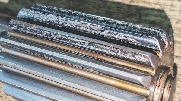
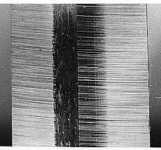
Heavy machinery operations frequently encounter gear failure pitting scuffing issues during high-load applications. These destructive surface phenomena degrade machinery components rapidly. Industrial power transmissions require optimal surface integrity to prevent premature mechanical breakdown. Microscopic cracks initiate beneath the tooth surface because of repeated cyclic contact stresses. Eventually, these cracks reach the surface and detach tiny metallic particles. This process creates small cavities on the active flanks. Conversely, scuffing represents a localized thermal breakdown of the lubricating oil film. High sliding velocities generate intense frictional heat under heavy contact pressure. Consequently, direct metal-to-metal contact occurs, leading to localized welding and tearing of tooth surfaces. Proper maintenance teams must identify these distinct surface phenomena to implement successful remedies.
The Critical Role of Surface Fatigue in Industrial Systems
Contact stress distribution dictates the mechanical life of power transmission components. Operating conditions often subject mechanical tooth flanks to severe cyclical shear stresses. These forces accumulate microstructural damage over millions of operating rotations. Eventually, the material reaches its shear fatigue limit. High-speed industrial gearboxes experience rapid stress cycles during continuous manufacturing operations. Engineers must evaluate these stresses using rigorous standards like AGMA 2101-D04. This standard helps predict surface fatigue life under specific load distributions. Application types influence stress concentration profiles across the active contact area. For instance, a Spur gear helical gear setup exhibits distinct contact line geometry. Helical tooth profiles distribute the load gradually compared to straight spur profiles. This design variation changes the localized sub-surface shear stress depth. Proper alignment maintains uniform stress distribution across the entire face width.
Assessing Contact Stress and Lubrication Film Breakdown
Elastohydrodynamic lubrication determines the thickness of the protective fluid film between teeth. Mechanical engineers often observe gear failure pitting scuffing under extreme pressure conditions. The specific film thickness depends heavily on lubricant viscosity and entrainment velocity. Operating temperatures directly affect the pressure-viscosity coefficient of industrial gear oils. High temperatures thin the lubricant, reducing its protective barrier capability. Consequently, the metal surfaces experience direct asperity contact during operation. This interaction accelerates wear and initiates micro-fractures on the metal surface. Proper oil selection prevents premature surface degradation by maintaining an adequate lambda ratio. A lambda ratio below one indicates boundary lubrication, which increases friction. Conversely, a lambda ratio above two ensures full-film separation of mating surfaces. Maintenance teams must monitor oil temperature to preserve this critical protective layer.
Identifying Micro-Pitting Characteristics on Gear Flanks
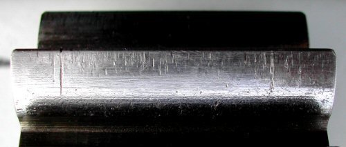
Surface roughness plays a significant role in early micro-pitting development. Microscopic peaks on the metal flanks experience localized stress concentrations during meshing cycles. These stress concentrations cause tiny surface-initiated cracks over time. The resulting damage appears as a dull, matte grey area on the tooth. Operators often mistake this initial fatigue for normal wear during routine inspections. However, this condition alters tooth profiles and increases dynamic vibration levels. Severe applications require specific gear configurations to handle these contact dynamics. For example, a Precision bevel gear worm gear system demands precise contact pattern adjustment. Bevel teeth require exact mounting tolerances to prevent localized end loading. Similarly, worm gears experience high sliding friction, accelerating micro-pitting if misaligned. Technical supervisors should utilize high-resolution borescope inspections to detect these early microscopic defects.
Addressing Severe Adhesive Wear and Scuffing Incidents
Severe thermal conditions lead directly to adhesive wear on contacting metal surfaces. Industrial operators resolve gear failure pitting scuffing by applying advanced heat treatment methods. When the lubrication film fails, asperities on opposing teeth weld together instantly. The ongoing rotation tears these microscopic welds apart, creating rough, scored marks. This destructive process occurs suddenly and causes rapid mechanical degradation. High sliding speeds combined with heavy shock loads accelerate this specific adhesive failure mode. Operators can identify scuffing by its characteristic torn appearance along the tooth profile. Proper lubrication with extreme pressure additives prevents these adhesive welds from forming. These chemical additives react with metal surfaces to form a sacrificial protective layer. This layer resists high temperatures and keeps the metal surfaces apart.
Mitigating Gear Failure Pitting Scuffing Through Metallurgy
Material selection dictates the ultimate resistance of industrial teeth against severe surface fatigue. Metallurgists specify case-hardened alloy steels like 18CrNiMo7-6 to maximize durability. This material choice provides a hard, wear-resistant outer shell with a tough core. Carburizing processes increase the surface hardness to sixty Rockwell C or higher. This high hardness resists both plastic deformation and initial micro-crack propagation. Additionally, shot peening induces beneficial compressive stresses on the tooth flanks. These compressive stresses effectively hinder the initiation and growth of fatigue cracks. Optimized grinding processes also minimize initial surface roughness, reducing localized friction during operation. Manufacturing engineers must adhere to strict ISO 6336 standards during these processes. These rigorous standards ensure consistent material properties and reliable performance in the field.
Crucial Parameters for Industrial Gear Design
Mechanical designers evaluate multiple parameters to minimize wear under severe operating conditions. Proper geometry optimization distributes contact pressure evenly across the mating tooth profiles. This balanced distribution prevents localized heat generation and stress concentration during high-speed rotation. Engineers must select appropriate pressure angles and helix angles for the application. These geometric selections directly influence the sliding velocity and contact ratio of the teeth. High contact ratios distribute the transmitted load over multiple teeth, reducing individual stress. Furthermore, modifying the tooth tip relief prevents dynamic interference during meshing. This modification ensures smooth transition and maintains a continuous protective oil film. Lubrication selection also plays a vital role in preventing mechanical wear under variable speeds. Designers must integrate these critical parameters during the initial engineering phase of gearbox creation.
Helix angle configuration
Active contact ratio
Surface finish tolerance
Tip relief modification
Evaluation of Mechanical Transmission Parameters
Proper system design reduces gear failure pitting scuffing risks in heavy industrial gearboxes. The previous list highlights critical factors that engineers must control to ensure machine reliability. Specifically, modifying helix angles shifts the contact line distribution, which decreases localized shear stress. A high active contact ratio ensures that multiple tooth pairs share the transmitted torque. Consequently, the individual tooth experiences lower contact stress, minimizing surface fatigue initiation. Tight surface finish tolerances reduce the peak-to-valley height of microscopic metal asperities. This optimization minimizes friction and prevents high flash temperatures that cause lubrication film failure. Finally, tip relief modifications accommodate mechanical deflection under high peak torque loads. These factors work together to enhance the mechanical integrity of heavy-duty transmissions.
Comparative Analysis of Surface Distress Severity
Industrial operators must distinguish different surface wear modes to select appropriate maintenance procedures. Quantitative comparison of operating parameters helps identify the transition from normal wear to severe distress. Various factors influence whether a transmission system experiences sub-surface fatigue or thermal bonding. Contact temperature and surface velocity dictate the primary failure modes in heavy duty machinery. The following comparison highlights key operational differences between micro-pitting and severe scuffing damage. Operating teams utilize this structured data to analyze field failures with high accuracy. Evaluating these operational thresholds improves diagnostic speed and prevents costly unexpected plant shutdowns. Additionally, this distinction assists engineers in selecting proper material and lubrication technologies. Maintenance teams can adjust operating parameters based on these distinct physical characteristics.
| Wear Mode | Primary Cause | Typical Location | Physical Appearance |
|---|---|---|---|
| Micro-Pitting | Surface fatigue | Dedendum area | Dull, matte grey frosted patches |
| Scuffing | Lubricant film welding | Addendum & dedendum tips | Severe tearing, localized scoring |
Detailed Mechanical Analysis of Surface Fatigue Tables
The compiled data in Table 1 illustrates the stark physical differences between these wear modes. Micro-pitting initiates primarily in the dedendum area due to high contact pressures and low sliding speeds. This low speed prevents the formation of a full elastohydrodynamic lubrication film. Consequently, the metal experiences microscopic cyclic fatigue, creating frosted patches over time. Conversely, scuffing occurs at the tips of the teeth where sliding velocities reach their maximum values. The high velocity generates extreme localized heat, causing the lubricant to fail instantly. This failure allows direct metal welding, which tears the surface during meshing. Technicians utilize advanced thermal sensors to detect these dangerous temperature spikes early. Operators must monitor these specific zones to catch wear before catastrophic mechanical failure occurs.
Operational Control of Lubricant Film Breakdown
Lubrication selection requires a comprehensive analysis of operating parameters under varying plant temperatures. High-viscosity base oils provide a thick fluid film that separates mating metallic teeth surfaces. However, excessive viscosity can increase viscous drag and generate unwanted heat within the gearbox. Synthetic oils offer superior performance because of their high viscosity index and low friction coefficients. These formulations maintain critical protective properties across a wide range of operating temperatures. Specialized extreme pressure additives build a protective surface layer during severe boundary lubrication conditions. The table below outlines typical lubrication performance indicators for various industrial oil formulations. Mechanical engineers utilize these precise metrics to select the ideal lubricant for specific applications. Proper oil selection maximizes machinery lifespans in aggressive production environments.
| Lubricant Type | Viscosity Index | Friction Coefficient | Load-Carrying Capacity |
|---|---|---|---|
| Mineral Oil | 95 - 100 | Medium | Standard |
| Synthetic PAO | 140 - 150 | Low | High |
| Synthetic PAG | 180 - 200 | Very Low | Excellent |
Analyzing Surface Fatigue Prevention Solutions
The performance metrics in Table 2 demonstrate the technological advantages of synthetic lubricants. High viscosity indexes ensure that synthetic oils maintain structural thickness at elevated operating temperatures. This stability prevents physical metal-to-metal contact when sliding speeds increase under heavy loads. Synthetic Polyalkylene Glycol oils offer exceptionally low friction coefficients, which reduces overall operating temperatures. Cooler operating conditions protect the surface from thermal bonding and subsequent scuffing damage. Furthermore, extreme pressure additives form active chemical barriers that resist extreme dynamic shear forces. These additives prevent metal welding under critical boundary lubrication regimes. Maintenance supervisors must evaluate these material characteristics to ensure maximum equipment reliability. Selecting the correct lubrication formulation directly prevents surface fatigue and localized mechanical failure.
FAQ
How does lubricant viscosity prevent pitting and scuffing?
High lubricant viscosity creates a robust physical film that separates mating gear teeth under load. This thick fluid barrier effectively reduces direct asperity contact, which prevents micro-pitting fatigue. Furthermore, proper viscosity dissipates heat efficiently, lowering localized flash temperatures during high-speed sliding. Cooler operating conditions prevent the thermal oil film breakdown that triggers adhesive scuffing wear. Maintenance teams should select viscosity grades based on extreme operating environment parameters. Using high-quality synthetic lubricants with high viscosity indexes ensures consistent protection across variable factory temperatures. This proactive lubrication management significantly extends the mechanical lifetime of heavy duty gear systems. Plant operators maximize equipment productivity by maintaining optimal oil properties over time.
What are the primary indicators of progressive gear damage?
Increased dynamic vibration levels represent the earliest sign of progressive surface wear in power transmissions. Mechanical defects disrupt smooth tooth meshing, generating unique vibration frequencies that technicians can measure easily. Additionally, regular oil analysis reveals metallic wear debris, indicating active surface fatigue within the gearbox. High concentrations of iron particles suggest progressive pitting or scuffing on the active flanks. Operators should also monitor operating temperatures, as sudden thermal spikes signal lubrication film failure. Early detection of these physical indicators prevents complete mechanical failure and costly emergency plant downtime. Consistent monitoring systems provide real-time diagnostic data to ensure continuous industrial operation.
Can surface coatings eliminate gear surface distress?
Advanced surface coatings significantly reduce surface distress but cannot entirely eliminate mechanical wear under extreme loads. Hard thin-film coatings, like diamond-like carbon, lower the friction coefficient of contacting steel flanks. This friction reduction minimizes heat generation, preventing localized thermal welding during severe high-speed operations. Furthermore, specialized coatings increase surface wear resistance, delaying micro-pitting fatigue under cyclical contact stress. However, these coatings require correct gear geometry and proper lubrication to function effectively. Operators must maintain clean operating systems to prevent abrasive particles from scratching the protective coated layer. Integrated engineering solutions combine metallurgy, coatings, and high-quality lubricants to achieve maximum durability.