How to Identify Pin Failure Bending Shear Stress
Heavy machinery relies on robust mechanical fasteners to maintain structural integrity. Engineers frequently encounter complex loading forces during high-stress industrial operations. These load conditions often trigger sudden component breakdown in critical joints. Specifically, a pin failure bending shear mechanism represents a significant operational risk. Severe physical damage occurs when lateral loads exceed calculated yield limits. Operators must monitor connector joints to prevent unexpected equipment downtime. Misalignment creates excessive localized pressure on critical connection surfaces. Proper stress distribution ensures long-term reliability in harsh working environments. Standard maintenance procedures require careful inspection of all load-bearing elements. Regular diagnostic checks help identify early microscopic cracks in steel joints. Addressing minor surface wear early prevents catastrophic structural failures later.
Mechanical Analysis of Shear Plane Deformations
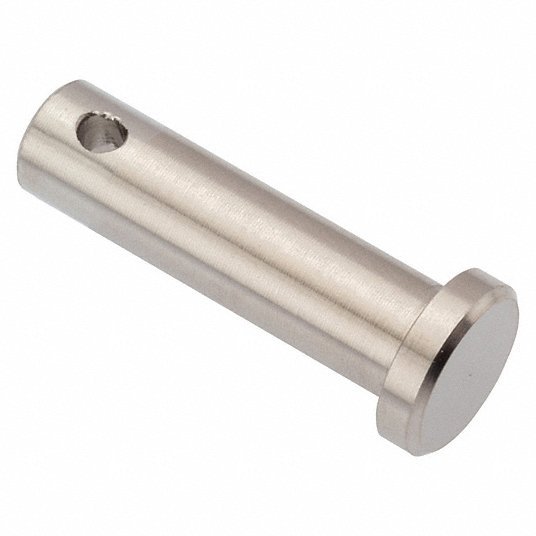
Designers select high-strength materials to withstand extreme transverse force demands. A stainless steel pin provides excellent corrosion resistance under wet conditions. However, even premium alloys deform when dynamic loads shift unexpectedly. Transverse forces generate intense stress concentrations across the primary contact plane. This mechanical action creates a distinct cutting effect on the fastener. Microscopic analysis reveals grain boundary sliding before the final rupture occurs. Engineers calculate shear area dimensions to ensure sufficient load-bearing capability. Overloading shifts the neutral axis and induces localized plastic deformation. Such physical changes compromise the structural alignment of the whole assembly. Heavy vibrations accelerate material degradation and promote rapid crack propagation. Preventive design margins must account for these unpredictable operating pressures.
Mechanical Specifications of Industrial Connection Materials
| Material Grade | Yield Strength (MPa) | Tensile Strength (MPa) | Shear Strength (MPa) |
|---|---|---|---|
| Alloy Steel 4140 | 655 | 850 | 490 |
| Carbon Steel 1045 | 310 | 565 | 340 |
| Stainless Steel 316 | 290 | 580 | 370 |
Performance Metrics of Standard Structural Alloys
The tabulated data highlights the diverse performance limits of common metals. High-strength alloy steel provides superior resistance against intense physical deformation. Choosing lower-grade options increases the risk of pin failure bending shear events. Shear strength values typically represent sixty percent of overall tensile strength. This mathematical ratio directs engineers during the initial joint design phase. Extreme operational loads easily overcome the yield capacity of softer metals. Consequently, carbon steels require larger diameters to support identical stress levels. Heat treatment processes significantly improve the mechanical durability of alloy components. Proper hardening increases resistance to micro-fracture propagation under severe friction. Selecting appropriate materials remains the primary defense against unexpected physical breakage. Industrial systems require specific grade materials to guarantee long-term operational safety.
Operational Life Expectancy Under Varying Load Ratios
| Load Ratio (%) | Stress Amplitude (MPa) | Cycles to Failure | Failure Probability (%) |
|---|---|---|---|
| 50% | 150 | 1,000,000 | 2% |
| 75% | 225 | 150,000 | 25% |
| 90% | 270 | 12,000 | 85% |
Analysis of Cyclic Fatigue and Expected Life Cycles
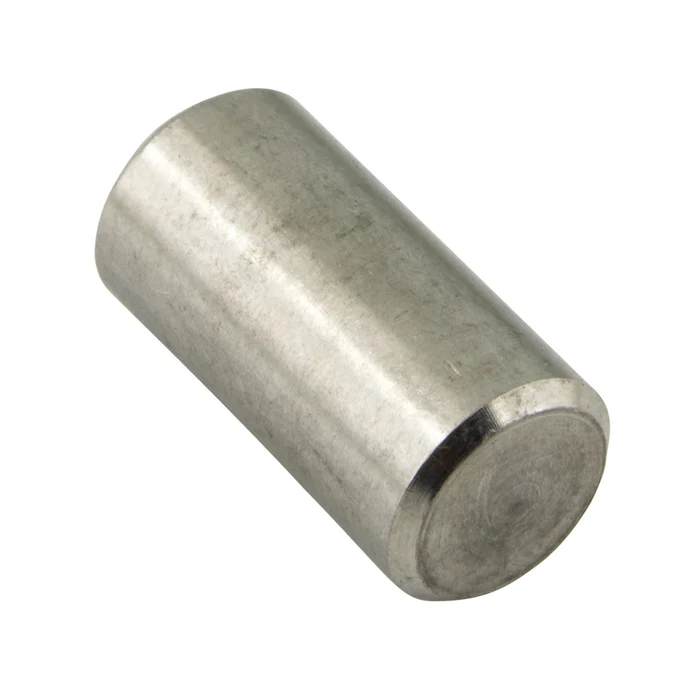
Repeated stress cycles rapidly exhaust the fatigue endurance limit of fasteners. A machining lock pin suffers severe fatigue when cyclic loads exceed limits. Higher stress amplitudes visibly reduce the expected operating lifespan of connectors. Operating near maximum yield capacity triggers rapid microstructural grain slippage. This localized damage eventually merges into a visible macroscopic fracture path. Sudden failure occurs when the remaining cross-section can no longer bear tension. Engineers utilize fatigue curves to predict components replacement schedules accurately. Proper lubrication reduces surface friction and minimizes localized thermal expansion. Controlling the operating load ratio represents a reliable method for extending service. Regular inspection protocols identify surface micro-cracks before they expand catastrophically. Heavy-duty applications require routine part rotation to distribute wear patterns evenly.
Primary Physical Factors Driving Mechanical Joint Wear
Excessive operational clearance within the coupling housing.
Insufficient material surface hardness causing surface friction.
Unaligned structural components applying uneven load pressure.
High ambient operating temperatures reducing tensile performance.
Engineering Solutions for Pin Failure Bending Shear Issues
These listed operational factors directly accelerate structural breakdown in mechanical joints. Misalignment forces the connector to bear unexpected axial bending moments. Severe friction wear rapidly degrades outer protective coatings on critical fasteners. Consequently, a pin failure bending shear occurrence becomes highly probable. High temperatures soften carbon steels, reducing their baseline resistance to cutting forces. Operators must maintain tight dimensional tolerances inside the connector housing. Using precision hardened sleeves prevents direct metal-to-metal friction during operation. Scheduled grease application keeps the contact surfaces clear of abrasive dust particles. Eliminating excess clearance minimizes impact forces when machines reverse physical direction. Proactive design adjustments guarantee stable stress paths throughout heavy load sequences. This preventative strategy significantly enhances the operating lifespan of modern machinery.
Comparing Radial and Axial Structural Load Paths
Complex mechanical assemblies distribute forces along multi-directional structural axes during heavy operation. Radial forces press perpendicular to the connector shaft, creating direct cutting stress. Axial forces pull parallel to the shaft, generating tension along the main body. Combined loads create dangerous bending moments that concentrate stresses at specific joints. Design engineers must map these load paths to locate potential structural weaknesses. Finite element analysis software provides precise visual models of stress concentration points. Modifying connector geometry reduces stress focus zones and improves overall mechanical safety. Adding chamfers to sharp corners distributes forces more evenly across the metal. These mechanical improvements significantly delay the initiation of microstructural fatigue cracks. Reliable load distribution ensures uniform material wear throughout the component service life. Well-designed connectors protect heavy industrial machinery from sudden and catastrophic operational failure.
Advanced Diagnostic Protocols for Heavy Fasteners
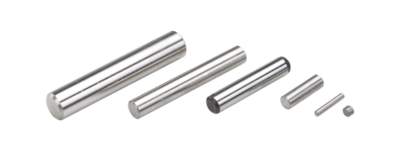
Industrial maintenance crews utilize advanced testing techniques to evaluate joint health. Ultrasonic testing devices locate internal material defects without damaging the connector. These sound waves bounce off internal cracks, revealing hidden microstructural flaws. Magnetic particle inspection reveals tiny surface fractures along high-stress areas. Technicians identify fatigue patterns early before critical components rupture completely. Replacing damaged components promptly prevents expensive unplanned facility shutdowns. Production supervisors schedule these diagnostic checks during routine operational stops. Clear inspection records help track component performance history over several years. This predictive data allows teams to adjust stress calculations dynamically. Reliable monitoring protocols ensure overall safety in high-stress manufacturing sectors. Modern hardware designs benefit greatly from these consistent quality assurance metrics.
Preventative Maintenance and Component Replacement
Designing robust machinery requires deep awareness of load-bearing joint stress profiles. Mechanical engineers must carefully calculate combined shear and bending forces. Ignoring cumulative material wear triggers sudden pin failure bending shear disasters. Selecting correct steel grades prevents premature fatigue in high-capacity equipment. Modern protective coatings shield vital mechanical connectors from rapid surface oxidation. Implementing systematic grease routines minimizes abrasive wear inside joint assemblies. Regular replacement schedules eliminate older components before critical limits occur. Operations managers prioritize safety by conducting thorough weekly inspections. This structured approach preserves machine alignment and maximizes daily factory output. Ultimately, proactive engineering choices guarantee long-term system stability and safety. Investing in quality parts reduces operational risks in complex industrial environments.
FAQ
What physical markers indicate sudden load component failure?
Operators identify component issues by checking for visible surface elongation. Heavy localized scoring along the load interface indicates severe mechanical friction. These marks often precede a full pin failure bending shear event. Surface cracks visible to the naked eye signal immediate replacement needs. Severe misalignment between connecting plates shows structural metal has already yielded.
How does mechanical fatigue limit industrial connector lifespan?
Fatigue limits define the maximum stress a metal survives without fracturing. Exceeding this critical threshold initiates microscopic damage within the alloy grain. These tiny microscopic cracks slowly expand under repetitive operating load conditions. High-frequency vibration accelerates this physical breakdown process in metal joints. Proper material selection ensures the connector resists early fatigue development. Heat treating components increases their yield limits against continuous stress cycles. Engineers reference standard S-N curves during the initial system development. Correct design margins keep operating forces safely below fatigue thresholds. Regular diagnostic testing identifies material degradation before complete rupture happens. Replacing fatigued parts proactively maintains safe daily factory performance levels. This preventative strategy significantly extends the operational lifespan of heavy machinery.
Why do temperature changes impact metal joint durability?
Extreme temperatures alter the physical properties of load-bearing metal alloys. High ambient heat reduces the ultimate yield strength of fasteners. This thermal expansion increases mechanical clearance inside the connector housing. Larger gaps allow components to shift, producing damaging impact forces. Conversely, freezing conditions make carbon steel brittle and prone to cracking. Brittle materials fracture rapidly when subjected to sudden transverse shock loads. Engineers choose specific steel grades to handle anticipated temperature ranges. Regular lubrication protects moving parts from localized thermal stress buildup. Monitoring thermal conditions helps operators schedule replacements before problems occur. Safe industrial performance relies on matching material specifications to environmental stresses. This careful planning avoids unexpected structural breakdowns in difficult operational climates.