Flanged bushing vs sleeve bushing selection plays a critical role in rotating machinery performance. Engineers rely on both components to reduce friction between moving parts. These bushings support shafts in demanding industrial environments. Proper selection directly affects alignment stability and wear rate. Flanged types provide axial positioning through an integrated flange structure. Sleeve types rely on cylindrical geometry for radial support. Design engineers often evaluate load direction before choosing either option. Incorrect selection may increase vibration and shorten service life. Industrial equipment such as conveyors depends heavily on correct bushing choice. Lubrication efficiency also depends on internal geometry and surface finish. Manufacturers optimize tolerances to ensure smooth rotation under pressure. Material selection further defines durability under heat and stress. Both types are widely used in automotive and heavy machinery systems.
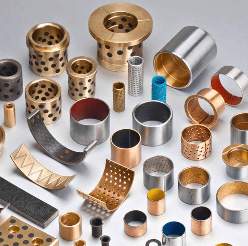
Flanged bushing vs sleeve bushing structural and functional comparison in machinery design

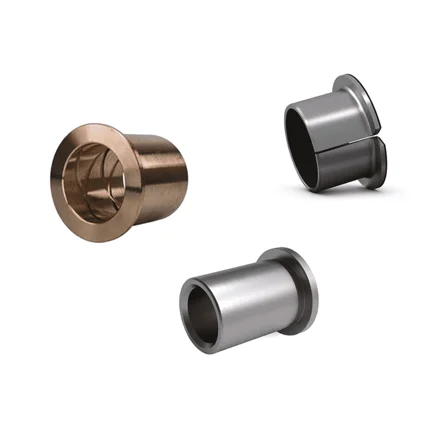
Material composition and engineering standards for industrial bushings
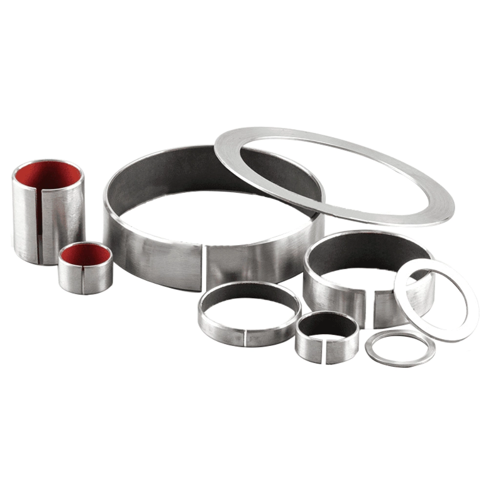
Material selection determines long-term durability and thermal resistance. Bronze alloys are commonly used in high-load environments. Polymer-lined composites reduce friction under dry running conditions. Steel-backed structures improve compressive strength in harsh systems. Industrial stainless steel bushing is used in corrosive environments requiring high stability. Surface hardness influences wear resistance and load distribution efficiency. ASTM B505 defines requirements for continuous cast copper alloys used in bronze bushings, while ISO 3547 specifies dimensions, tolerances, and testing methods for plain bearings. Lubrication compatibility varies depending on material porosity. Self-lubricating bushings reduce maintenance frequency in automated systems. Thermal expansion must be considered in precision assemblies. High-speed applications require materials with low friction coefficients. Chemical exposure resistance is critical in marine equipment. Manufacturers test fatigue resistance under cyclic loading conditions. Proper material pairing reduces seizure risk in continuous operation.
Installation behavior and alignment stability in machinery systems
Installation methods affect long-term performance and maintenance cycles. Press-fit installation ensures tight engagement with housing surfaces. Shoulder-stop designs improve axial positioning accuracy. flanged bushing vs sleeve bushing installation differs in alignment control mechanisms. Flanged designs simplify axial fixation without additional components. Sleeve designs rely on housing shoulders for positioning stability. Misalignment during installation increases localized stress concentration. Proper tooling ensures uniform insertion force distribution. Maintenance accessibility varies depending on assembly design. Field replacement efficiency is important in production environments. Lubrication channels must align correctly during installation. Improper seating may reduce load-bearing capacity significantly. Vibration resistance improves with correct press tolerance selection. Assembly sequence directly affects final mechanical stability.
Load capacity and wear behavior in flanged bushing vs sleeve bushing systems
Flanged bushing vs sleeve bushing performance differs under radial and axial stress. Flanged types handle combined load conditions more effectively. Sleeve types focus primarily on radial load distribution. Wear patterns depend on contact surface area and lubrication quality. Continuous operation generates heat at friction interfaces. Boundary lubrication reduces metal surface degradation. Micro-motion between surfaces accelerates wear formation. Material hardness influences deformation resistance under pressure. Dynamic loads require consistent energy absorption capability. Overloading leads to ovalization in sleeve designs. Flanged structures reduce axial displacement under cyclic stress. Fatigue resistance is critical in rotating equipment systems. Lubricant breakdown increases friction coefficient rapidly. Proper load matching extends service life significantly.
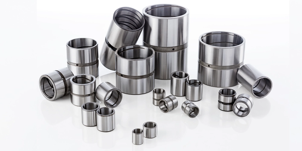
Industrial application scenarios and usage environments
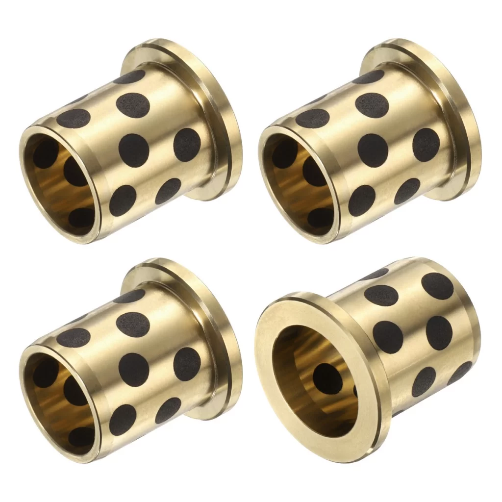
Machinery selection depends heavily on operational environment conditions. Automotive suspension systems use bushings for vibration isolation. Heavy equipment relies on durable pivot joint designs. Hydraulic cylinders require stable guidance components. Conveyor rollers depend on low-friction rotation support. Brass bushing with oil groove is commonly used in low-speed machinery requiring continuous lubrication. Mining equipment demands high shock resistance components. Agricultural machinery operates under dusty and abrasive conditions. Pneumatic systems require smooth linear motion support. Marine equipment needs corrosion-resistant material selection. Production lines prioritize low maintenance downtime. Robotics applications require high positional accuracy. Temperature fluctuations affect material expansion behavior. Industrial environment selection determines lubrication strategy.
Selection criteria for flanged bushing vs sleeve bushing in engineering design
Flanged bushing vs sleeve bushing selection depends on load direction and assembly constraints. Engineers evaluate radial and axial force distribution first. Space availability influences design feasibility significantly. Cost efficiency affects large-scale production decisions. Maintenance frequency determines material and lubrication choice. Finite stress modeling helps predict failure points. Safety factors ensure operational reliability under peak load. Noise reduction requirements influence surface finishing methods. Speed of rotation affects friction heat generation. Environmental exposure determines corrosion resistance needs. Service life expectations guide material selection. Manufacturing tolerances influence final assembly accuracy. Design optimization balances performance and cost efficiency. Incorrect selection increases system failure probability.
Common engineering mistakes in bushing selection and system design
Design errors often arise from incorrect load assumptions. Ignoring axial forces leads to premature failure. Poor lubrication planning increases friction damage. Incorrect housing tolerances reduce alignment stability. flanged bushing vs sleeve bushing confusion causes design inefficiency. Overlooking thermal expansion leads to binding issues. Improper material pairing increases wear rate. Installation errors reduce operational lifespan significantly. Insufficient clearance causes overheating during operation. Excessive clearance increases vibration levels. Maintenance neglect accelerates performance degradation. Wrong geometry selection impacts system efficiency. Engineering validation prevents long-term mechanical failure.
Performance comparison tables for industrial bushing systems
| Feature | Flanged Bushing | Sleeve Bushing |
|---|---|---|
| Axial Load Control | High | Low |
| Radial Load Capacity | Medium | High |
| Installation Complexity | Moderate | Low |
| Cost Level | Higher | Lower |
Engineering interpretation of performance comparison above
The table highlights structural and functional trade-offs between designs. Flanged types excel in axial stability and positioning control. Sleeve types offer simpler integration and lower manufacturing cost. Selection depends on system load direction priorities. Engineers balance performance and budget constraints carefully.
| Application Area | Recommended Type | Reason |
|---|---|---|
| Heavy Machinery | Flanged Bushing | Axial stability requirement |
| Light Equipment | Sleeve Bushing | Cost and simplicity |
| Corrosive Environments | Stainless Variant | Corrosion resistance |
| Low-Speed Systems | Oil Groove Bronze | Continuous lubrication |
Application-based interpretation of selection matrix
The second table connects real-world environments with design choices. Different industries prioritize distinct mechanical requirements. Heavy machinery demands stability under combined loading conditions. Light equipment values cost efficiency and simplicity. Corrosive environments require stainless-based solutions. Low-speed systems benefit from continuous lubrication structures.
Conclusion on flanged bushing vs sleeve bushing engineering decisions
Flanged bushing vs sleeve bushing selection depends on system geometry and load behavior. Engineers must evaluate operational conditions before final design decisions. Proper selection improves durability, efficiency, and mechanical stability. Incorrect choices increase maintenance cost and system downtime. Performance optimization relies on balanced engineering judgment.
FAQ
When should a flanged bushing be preferred over a sleeve design?
A flanged bushing is preferred when axial positioning control is required. It prevents shaft movement along the rotational axis effectively. Engineering systems with combined loads benefit from flange structures. Installation environments with limited space also favor compact axial locking. Flanged designs reduce dependency on additional retaining components. They improve alignment stability in high-vibration machinery systems. Sleeve designs cannot independently restrict axial displacement. Therefore, flanged structures are used in precision mechanical assemblies. Selection depends on force direction and housing geometry. Proper evaluation ensures longer service life and reduced wear issues.
Can sleeve bushings handle axial loads effectively in machinery systems?
Sleeve bushings primarily handle radial loads rather than axial forces. Their cylindrical shape distributes stress evenly around the shaft. Limited axial resistance makes them unsuitable for strong thrust loads. Engineers sometimes combine sleeves with additional mechanical stops. This improves stability in complex assembly configurations. Lubrication quality strongly affects performance under mixed loading conditions. Excess axial force may cause edge wear and deformation. Proper clearance design reduces friction under dynamic operation. Material choice also influences load tolerance capacity. System design must consider force direction carefully.
What are the most common failure modes in both bushing types?
Common failure modes include wear, deformation, and lubrication breakdown. Excessive load causes surface fatigue and dimensional instability. Misalignment increases localized stress and uneven wear patterns. Contaminants accelerate abrasive damage within contact surfaces. Thermal expansion may cause binding during continuous operation. Insufficient lubrication increases friction and heat generation. Material fatigue leads to cracking under cyclic loads. Improper installation reduces alignment accuracy significantly. Design mismatch between load and structure causes premature failure. Regular inspection reduces risk of catastrophic system breakdown.